


LEDs
The table below describes the activity of the LEDs.
Label
Color
Activity
Description
Power
Green
On
Power is supplied to the hub.
Off
Power is disconnected.
Rx/Tx/
Green
Blinking
Packet transmission or reception is
Collision
occurring on the port. The blinking
action corresponds to the number of
packets that are transmitted or
received.
Yellow
Blinking
Data collision is occurring on the
port. The blinking corresponds to the
number of collisions. When a collision
occurs, the connected device pauses
and transmits again after waiting a
specified time.
100 Mbps Green
On
The port is operating in 100 Mbps
mode.
Off
The port is operating in 10 Mbps
mode.
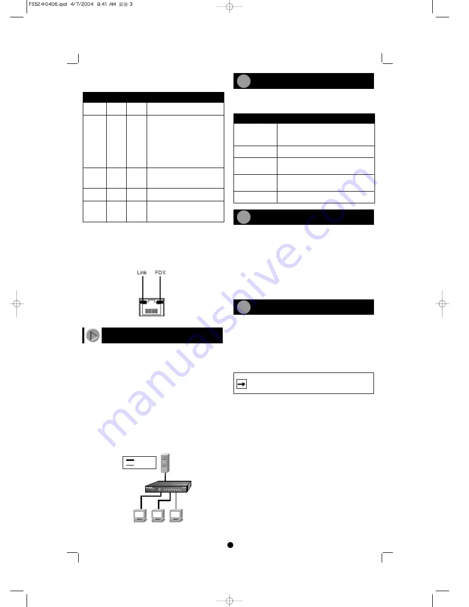
Link
Green
On
A valid link is established on the port.
Off
A link is not established on the port.
FDX
Green
On
The port is operating in full-duplex
mode.
Off
The port is operating in half-duplex
mode.
RJ-45 Network Ports with Built-in LEDs
All ports on the switch are 10/100 Mbps capable autosensing Ethernet
ports. Each port supports only unshielded twisted pair (UTP) cable
using an 8-pin RJ-45 plug. Each port uses RJ-45 connectors that have
two LEDs-the Link LED and the FDX LED.
Applications
The Model FS516/FS524 switch is designed to provide flexibility in
configuring your network connections. Each switch can be used as a
standalone device or can be used with 10 Mbps or 100 Mbps hubs or
other interconnection devices in various configurations. The configu-
ration examples in this section illustrate the integration of the switch-
es in network environments of all sizes and types. These examples
include a network of a few workstations connected to a printer or a
segmented network with multiple users or workgroups and other net-
working devices.
Desktop Switching
The Model FS516/FS524 switch is used as a desktop switch to build a
small network that enables users to have 100 Mbps access to a file
server. If a full-duplex adapter card is installed in the server or PC, a
200 Mbps connection is possible on the port where the server or PC is
connected.
Before you begin installing your switch, prepare the installation site.
Make sure your operating environment meets the operating environ-
ment requirements of the equipment.
To install your switch on a flat surface, you do not need any special
tools. Be sure the switch is positioned with at least 2 inches of space
on all sides for ventilation.
To install the switch in a rack, first attach the mounting brackets to
the side of the switch. Insert the screws provided in the rack mount kit
through each bracket and into the bracket mounting holes in the
switch. Tighten the screws with a #1 Phillips screwdriver to secure
each bracket. Align the mounting holes in the brackets with the holes
in the rack and insert two pan-head screws with nylon washers
through each bracket and into the rack. Tighten the screws with a #2
Phillips screwdriver to secure the switch in the rack.
Before connecting the switch, be sure you review "Applications" for
information about determining the appropriate configuration for your
networking needs. Refer to the following steps and illustration when
connecting the switch. Each of the steps has a corresponding refer-
ence number in the illustration.
To connect devices to the switch:
1.
Connect the devices to the 10/100 Mbps ports on the switch,
using Category 5 UTP cable and an RJ-45 plug.
Characteristic
Requirement
Temperature
Ambient temperature between 0
0
and 40
0
C
(32
0
and 104
0
F).
No nearby heat sources such as direct
sunlight, warm air exhausts, or heaters.
Operating humidity
Maximum relative humidity of 90%,
noncondensing.
Ventilation
Minimum 2 inches (5.08 cm) on all sides for
cooling.
Adequate airflow in room or wiring closet.
Operating conditions At least 6 feet (1.83 m) to nearest source of
electromagnetic noise (such as photocopy
machine).
Power
Adequate power source within 6 feet
(1.83 m).
Prepare the site
Install the Switch
Connect the Devices
1
2
3
Note:
Ethernet specifications limit the cable length between
your PC or server and the switch to 328 feet (100 meters) in
length.
2
100 Mbps
10 Mbps
Key
FVL328 ProSafe
TM
High-Speed VPN
Firewall


