

PORT
2
PORT
1
LINK
ACT
LINK
ACT
M
1
2
1
MLOM
PC
Ie
1
PC
Ie
2
P
S
U
2
R
M
S
-2
00
O
K
770W AC
770W AC
PORT
2
PORT
1
LINK
ACT
LINK
ACT
M
1
2
1
MLOM
PC
Ie
1
PC
Ie
2
P
S
U
2
R
M
S
-2
00
O
K
770W AC
770W AC
2
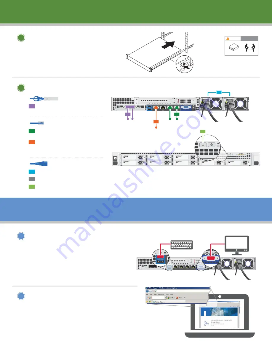
Cable the node
1
Configure the node using
Terminal User Interface (TUI)
• Attach keyboard to the USB port and
monitor to the VGA port on the node.
Note: The node should be powered on.
• Refer to the
SolidFire Element Setup Guide
for instructions on
Configuring Nodes
Using the TUI
.
2
Create a new cluster or add
a node to an existing cluster
using the Element OS WebUI
• From a Windows client on the same network
as the newly configured node, access the
Element OS by entering the node's IP address.
• Refer to the
SolidFire Element Setup Guide
for instructions on
Creating a New Cluster
.
1
Install hardware
Install hardware
|
2
Configure the node
|
3
Connect 10GbE cables to
the storage network switch.
Connect 1GbE cables to
1GbE management switch.
Connect 1GbE cable to
out-of-band management
(DHCP) switch.
Connect both power cords to the node.
Plug the power cords to a suitable power outlet.
Power on the node.
1
2
3
4
5
6
To storage
network switch
To 1 GbE
management switch
To out-of-band
management
(DHCP) switch
BACK VIEW
1
2
3
4
FRONT VIEW
10 GbE cables
(
PN 112-00299 or 112-00300 or 112-00301)
Ethernet cables
(
PN 112-00196)
Power cables
5
Install the rails and the node following the
instructions for
Installing a node in a rack
in the
Cisco UCS C220 M4 Server Installation
and Service Guide
.
LIFTING HAZARD
CAUTION
38 lb. (17 Kg)
Keyboard
connection
6
PORT
2
PORT
1
LINK
ACT
LINK
ACT
M
1
2
1
MLOM
PC
Ie
1
PC
Ie
2
R
M
S
-2
00
O
K
770W
PORT
2
PORT
1
LINK
ACT
LINK
ACT
M
1
2
1
MLOM
PC
Ie
1
PC
Ie
2
R
M
S
-2
00
O
K
770W AC
Monitor
connection
5
http://www.netapp.com/us/media/SolidFire-Element-OS-9-Setup-Guide.pdf


