46
NetApp AltaVault Cloud Integrated Storage Installation and Service Guide for Physical Appliances
Beta Draft
System components
Using LEDs to check the status of the system
2.
Use the following table to understand the system LEDs:
3.
Use the following table to understand the AltaVault appliance system components on the chassis front:
Component
Description
1
System LEDs
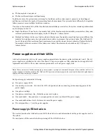
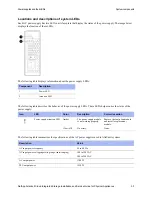
When the bezel is in place, the LEDs are arranged horizontally in the following left-to-right order:
• Power
• Fault (System Attention LED)
• Controller A activity (controller installed in the top bay only with no secondary controller)
Note:
When the bezel is removed, the system LEDs on the chassis are arranged in the same order as on
the bezel, but in a top-to-bottom vertical orientation.
Component
Description
Bezel
The bezel covers the front of the AltaVault system chassis. From the bottom of the front
bezel, you can see four system LEDs (arranged horizontally) that indicate the status of the
system.
Fan modules
There are six redundant and hot-swappable fan modules installed in slots A1 through A3 and
B1 through B3.
The bottom row contains a blank.
You have to remove the front bezel to see the fan modules. The Attention LED is set to
Amber if the fan module is not working properly.
System LEDs
The chassis has four LEDs (arranged vertically) that indicate the status of the system:
• Power
• Attention
• Activity A (Controller)
• Activity B (unused in AltaVault)
These LEDs are located behind the bezel. Remove the front bezel to see these LEDs.
The system LEDs and the LEDs visible when the bezel is installed are the same, except that
the bezel LEDs are aligned horizontally and the system LEDs are aligned vertically. Both
sets of LEDs provide the same information about the system.
Chassis handles
The chassis has two handles on each side that assist with lifting the system. The handles are
integrated into the chassis and fold flush when not in use.
Summary of Contents for AltaVault Cloud Integrated Storage 4.1
Page 2: ......


