N11
Hardware User Guide
Copyright © Neoway Technology Co., Ltd
24
When the module is running, NET_LIGHT outputs PMW waves of duty cycle varying with the status
of the module and drives an LED indicator to blink at different frequencies.
For how to set the LED indicator, see
Neoway_N11_AT_Commands_Mannual
.
3.6
RF Interface
3.6.1
RF Design and PCB Layout
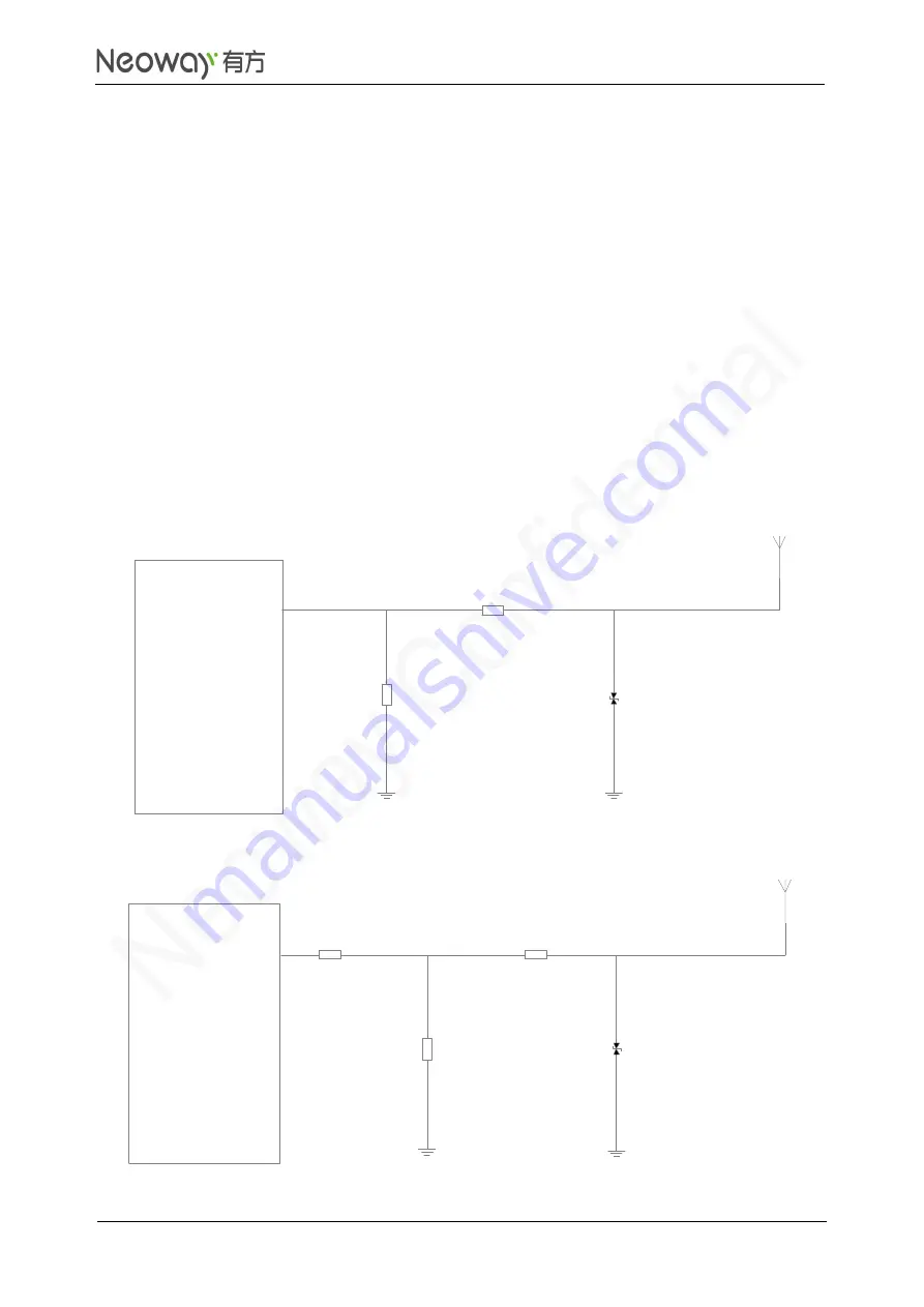
ANT_MAIN of N11 requires a characteristic impedance of 50 Ω, and the impedance of the traces
should be controlled between the pins and antenna. To ensure the RF performance, add an
impedance matching circuit, such as L network, T network, or pi network in between. Pi network is
recommended.
Figure 3-21
L network
ANT_MAIN
N11
module
Z1
Z2
D1
Figure 3-22
T network
ANT_MAIN
N11
module
Z1
Z2
D1
Z3


