background image

Genesis Manual  Rev1.6               Copyright 2018,  Nellis Engineering, Inc.  

16

Lubricate  the  recharge  connector  on  the  nose  as  needed  with  silicone  spray  lubricant  or  a  very, 
very  small  amount  of  silicone  grease.  Too  much  grease  will  attract  sand  and  dirt  which  can 
damage the sealing surfaces of the connector and also become packed in the bottom of the cover 
and charger cable holes, preventing good contact. 


CAUTION 

Do not apply any petroleum based lubricants to the recharging 

connector plug, cover or charger cable. 


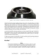
If the vacuum/pressure test plug on the nose has been removed, inspect the o-ring carefully and 
replace if necessary.  Use a Buna-N, size -904, 70 or 90 durometer o-ring and a generous amount 
of silicone grease.  Install the plug and then wipe off the excess grease. 
 
The  thick  washers  used  on  the  12  screws  that  fasten  the  nozzle  struts  to  the  tail  cone  are  zinc 
anodes.    Should  they  develop  a  white  powdery  film,  clean  them  with  a  toothbrush  or  soft  wire 
brush  following  a  dive,  as  the  powdery  material  will  be  softer  when  wet.    The  white  powdery 
residue must be cleaned off for them to properly function as anodes.  Do not apply any lubricant 
or  protectant  coatings  to  the  anodes.    They  are  sacrificial  and  must  be  allowed  to  corrode,  to 
protect the DPV.  You may remove these 12 screws to inspect for corrosion on the threaded holes 
in  the  tail  cone.    Grease  the  holes  (using  a  toothpick  to  get  the  grease  in  side)  and  screws  with 
AquaShield  (formerly  know  as  AquaLube)  marine  lubricant  from the DA Stuart  Company  prior  to 
reassembly and replace the anodes as necessary.  Torque screws to 35 in-lb.  Additionally, check 
the torque on the 12 screws that attach the nozzle struts to the nozzle (torque 30 in-lb).   


Vacuum & Pressure Testing 


The test port on the nose of the DPV can be used for leak testing the DPV.  A test gauge assembly 
can  be  ordered  from  the  factory  or  assembled  by  the  owner  with  off-the-shelf  fittings.    A  list  of 
materials is available on request.  A bicycle pump is all that is required for a simple pressure test.  
 

Procedure 

 
1.  Remove the battery assembly from the DPV and also the test port plug from the nose,  
      using an 11/16" socket. 
 
2.  Remove the center screw from the row of battery connectors on the tail section.   
     This will allow air to flow freely between the tail and body.  Failing to remove this screw can  
     give a false indication of a leak.   
 
3.  Install the body onto the tail section and install the lock strips as usual. 
 

Summary of Contents for Logic Genesis

Page 1: ...Genesis Manual Rev1 6 Copyright 2018 Nellis Engineering Inc Genesis Genesis Genesis Genesis Diver Propulsion Vehicle DPV Owner s manual ...

Page 2: ...would be leaving essential safety information out of the water which is no different than leaving essential dive safety equipment on the shore where it will do you no good when you need it most If you have any question contact the factory for guidance Table of contents Page Warnings Cautions 3 Assembly 5 Batteries and charging 7 Tow Cord 9 Trimming 10 Operation 10 Post Dive 13 Care Maintenance 14 ...

Page 3: ...fe location free of flammable materials under direct supervision and only using the supplied charger Do not attempt to charge the batteries immediately after fully discharging them at hi power The batteries heat up the most during the end of a deep discharge and should be allowed to cool for one hour before recharging For the best battery life avoid deeply discharging the batteries if possible WAR...

Page 4: ...nd also damaging the coupling CAUTION Avoid running the DPV until battery cutout Deeply discharging the battery shortens the battery life and can lead to over discharge of the batteries Should the DPV be run until cutout remove the recharge plug cover on the nose of the DPV after exiting the water and recharge the batteries at your earliest opportunity CAUTION Ensure the DPV recharge connector cov...

Page 5: ...strip before pulling it free of the housing It may be necessary to compress the tail section into the body to free the locking strip as a slight pressure inside the DPV can cause them to bind With the locking strips removed stand the DPV on its nose and lift the tail section off of the body Note It is possible to have a slight vacuum or pressure inside the DPV body that prevents the tail section f...

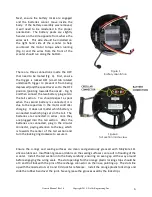
Page 6: ...apacitors in the motor controller charging It does not matter which battery is connected to which plug set on the tail The batteries are connected in series once they are plugged into the tail section After the batteries are connected plug in the circular connector paying attention to the key which is towards the center of the tail section and turn the locking ring clockwise to secure it Ensure th...

Page 7: ...or controller and should be thought of as an ignition key for an automobile When the cover is installed the batteries will begin discharging slowly so do not leave the cover installed when storing the scooter or the batteries may be damaged by over discharge Remove the cover at the end of the diving day or after exiting the water if the DPV is run until battery cutout The recharge plug cover is ra...

Page 8: ...an indication of low battery voltage and a possible over discharge Reseat all the connectors and try charging again If they still do not begin charging disconnect the batteries from the tail section and contact the factory CAUTION The batteries should never be charged directly from the supplied charger with any kind of adapter There is a protection circuit in the DPV tail section that prevents pow...

Page 9: ...tor is accidentally left installed for days or weeks or the scooter is stored for long periods months without use The proper operation of the batteries can be identified easiest by ensuring that the green LEDs on the charger both turn red when the batteries begin charging If one or both LEDs remain green for more than 60 seconds after connecting the charger it is an indication that one or both of ...

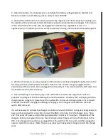
Page 10: ...l yet This is done with the DPV open and the batteries removed for the body 5 Once everything is connected plug in the wall socket and wave the magnetic end of the propeller coupling over the blue rectangular area show above A battery that is charging will stop charging when a magnet is passed over the reed switch and resume charging when it is removed A battery that is NOT charging should begin c...

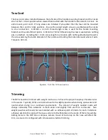
Page 11: ...othing attached will result in the screw piercing the inside diameter of the nozzle and cracking the material around where it exits Torque to 30 in lb Figure 6 Taut line hitch sequence Trimming The DPV should be trimmed with weight inside so as to have the proper buoyancy characteristics in the water Typically DPVs are trimmed neutral to slightly positive when diving open water and neutral when di...

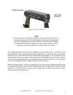
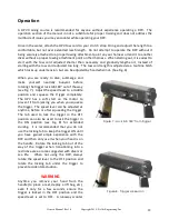
Page 12: ...rally buoyant before rotating the trigger lock tab 180 out of the way see Fig 7 Adjust the speed lever to a middle position and squeeze the trigger completely The DPV has a soft start on the motor to prevent it from jerking you when you squeeze the trigger The speed lever can be adjusted at anytime before or after squeezing the trigger The tab used to lock the trigger in the OFF position can also ...

Page 13: ...or boat It should also be noted that most divers do not use more than 40 lbs of thrust in regular operation and you may never notice the reduction in power if you are already operating below the reduced power level With proper dive planning you should never be operating in the last 10 of the battery capacity While scootering around at top speed is fun it consumes 5 7 times as much power as normal ...

Page 14: ... water or leave tied off to something in the cave or wreck to be retrieved later A small amount of water in the body is generally not a concern even if it is salt water Remove the battery module and dry it Also wipe out the inside of the body If the leak source can be located and repaired it is recommended to still let everything air dry at least 12 hours in a warm dry environment before closing t...

Page 15: ...ies below 40 capacity recharge the batteries before storing the DPV as suggested in the Recharging section of the manual If you will be storing the DPV for more than one month before the next dive it is recommended to open the DPV and disconnect the batteries This will prevent the need for a maintenance charge being performed due to a very small voltage drain needed by the charger to sense the bat...

Page 16: ...es Do not apply any lubricant or protectant coatings to the anodes They are sacrificial and must be allowed to corrode to protect the DPV You may remove these 12 screws to inspect for corrosion on the threaded holes in the tail cone Grease the holes using a toothpick to get the grease in side and screws with AquaShield formerly know as AquaLube marine lubricant from the DA Stuart Company prior to ...

Page 17: ...e gauge assembly and remove it Reinstall the test port plug and the screw for the battery connectors Data Loggers If you wish to install a data logger to monitor power consumption it will need to be configured per the diagram below Fig 10 The scooter voltage can be as high as 67 0V and the current as high as 20A so the data logger needs to be rated accordingly You will need to make a jumper to con...

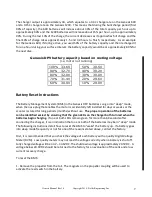
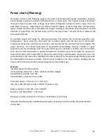
Page 18: ... the right to the power estimate You should never plan on using 100 of the battery capacity 70 80 is a good capacity to plan on and leaves room for issues that may arise but 66 is used for the rule of thirds Even more conservative battery capacity calculations should be used if you might be required to tow another diver with a dead DPV as that will increase drag and the power required to cover the...

Page 19: ...ate single tank 0 25 50 75 100 125 150 175 200 225 250 275 300 Speed Ft Min 0 100 200 300 400 500 600 700 800 900 1000 1100 1200 Power Watts Input Power vs Static Thrust 0 100 200 300 400 500 600 700 800 900 1000 1100 1200 10 0 20 0 30 0 40 0 50 0 60 0 70 0 80 0 90 0 Thrust lbs Watts ...

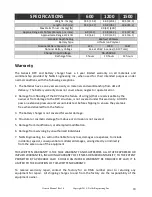
Page 20: ...ering Inc will not be liable for any loss damages or expenses to include incidental special consequential or collateral damages arising directly or indirectly from the sale or use of the equipment THIS WRITTEN WARRANTY IS THE SOLE WARRANTY AND SUPERSEDES ALL OTHER EXPRESSED OR IMPLIED WARRANTIES INCLUDING WARRANTY OF FITNESS OR MERCHANTABILITY TO THE EXTENT PERMITTED BY APPLICABLE LAW SHOULD AN IM...

Reviews:

Related manuals for Logic Genesis