


10
•
Place the pre-compressed graphite rings (back seals)(195) onto
the seat.
•
Place seal ring (braided graphite) (129) into the groove of the ball
seat.
•
Place the ball seats into the body and the body cap using plastic
or wooden mallet or if necessary, using a hydraulic press.
All versions:
•
Place a trunnion bearing (99) into each trunnion plate (89) coun-
terbore.
•
Place a bearing spacer (91) over each ball trunnion.
•
Fit a trunnion plate over each ball trunnion until the plate rests
against the bearing spacer (91). This operation must be per-
formed with care and without excessive force or the bearing will
be damaged. It may be necessary to tap the plate on with a plas-
tic mallet.
•
Align the trunnion plates (89) relative to the ball port in the closed
position.
•
With the ball (3) in the "closed" position, lower the ball/trunnion
plate subassembly into the body (1).
NOTE:
This procedure is
critical and careful attention is a must. The outside diameter of
the trunnion plates must pilot in the body counterbore. Carefully
lower the subassembly until a trunnion plate enters the counter-
bore (Usually one trunnion plate will enter the counterbore and
the other will be out of position.) Use a plastic mallet or a block of
wood to rotate the second trunnion into position. Once trunnion
plates are aligned, lower the subassembly until the trunnion
plates are seated in the bottom of the counterbore.
•
Slide the thrust bearings (70=thinner, 71=thicker) over the shaft
(5). See the exploded view for proper orientation.
•
Insert shaft subassembly through the bonnet (8) and install pack-
ing (69). Refer to Fig. 11 for proper orientation of packing.
•
Install the gland (9) over shaft (5) and gland studs. Install the disc
springs sets (150) and the gland stud nuts (18) on studs and
tighten "finger tight."
•
Install the bonnet gasket (66) and the bonnet subassembly over
the bonnet studs (10). Note the correct shaft position! Lubricate
the threads of studs (13) and tighten the nuts (17) according to
values in Table 2.
•
Install the body gasket (65) in the body groove.
•
Place the body cap (2) carefully over the body studs (12) and the
body (1). See that the flange holes are aligned acc. to the mark
made during the dismatling. Take care not to damage the body
gasket and the seat (7) in the body cap.
•
Fasten the body nuts (16). Tighten the nuts gradually, always
switching to other side of the valve after every nut. The recom-
mended torques are given in Table 2. The flange faces must in
even contact with each other.
•
Mount the key (10).
•
Cycle the valve slowly a couple of times to insure correct position
of the ball between the two seats.
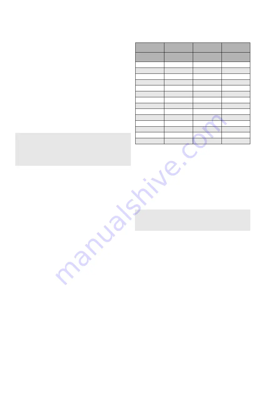
Tightening torques of the body joint bolting
•
Tighten the gland nuts (18) acc. to Section 4.2 . Pull on the shaft
(5) while tightening to assure that shaft and thrust bearings are
always in contact with the body. Check for leakage once the
valve is pressurized..
•
Install the valve in the pipeline as carefully and accurately as
when removing it. Follow the instructions given in Section 3.
5 TESTING THE VALVE
We recommend that the valve body be pressure tested after the
valve has been assembled.
The pressure test should be carried out in accordance with an
applicable standard using the pressure rating required by the
pressure class or flange drilling of the valve. The valve must be in an
half-open position during the test.
If you also want to test the tightness of the closure member, contact
the manufacturer.
NOTE
:
The shaft will fit into the ball in one position only. There’s a larger
cog in the splined shaft or added cog in square end shaft and a
matching groove in the ball shaft bore. It is essential to note the
groove’s position during the next assembly step.
Material
ASTM A320 gr.
L7M
ASTM A193 gr.
B8M cl. 1
ASTM A193 gr.
B8M cl. 2
Bolt Size
Tightening
Torque (Nm)
Tightening
Torque (Nm)
Tightening
Torque (Nm)
M8
25
11
31
M10
50
22
60
M12
85
38
100
M14
140
61
170
M16
210
95
260
M18
290
130
350
M20
420
190
420
M22
560
250
560
M24
720
320
720
M27
1100
480
870
M30
1400
650
1200
M33
2000
880
1200
M36
2500
1100
1600
M39
3300
1500
2100
NOTE: Threads must be well lubricated
NOTE: ASTM A193 B8M cl.1 utilized in sizes 2"-16", ASTM A193 cl.2 utilized
in sizes 18"-24"
CAUTION
:
Pressure testing should be carried out using equipent conforming
to the correct pressure class!


