10
3 R 71 EN - Issue 9/2020
•
Detach the retainer plates (42).
•
Detach the gland packings (20).
•
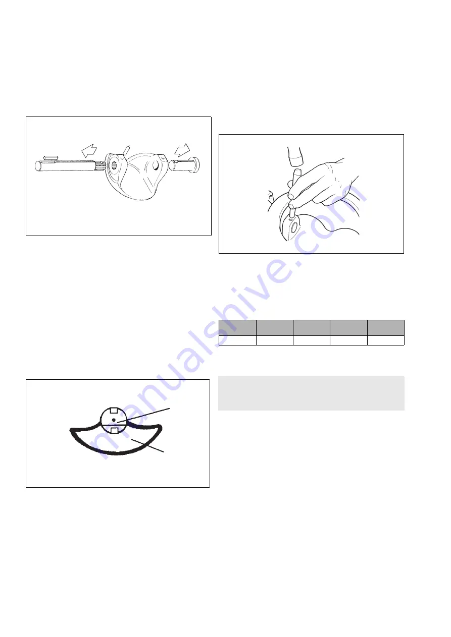
Remove the shafts (11 and 12), Fig. 24.
•
Lift the segment from the body.
•
Remove the bearings (15 and 16) and clean the bearing spaces.
•
Remove the seat by pushing it evenly inside the body.
4.7 Inspection of removed parts
•
Clean the removed parts.
•
See if the shafts (11, 12) and bearings (15, 16) are damaged.
•
Check if the sealing surfaces of the segment and the seat (4) are
damaged.
•
If necessary, replace the parts with new.
4.8 Assembly
•
Put the bearings (15, 16) in their places.
•
Mount the seat as explained in Section 4.5.2.
•
Mount the segment in the body in the closed position. Press the
segment to fit the shaft (12).
•
Install the drive shaft (11). Note the location of the pin hole and
the keyway. See Fig. 25.
•
Please note the depth of the hole (L) for the conical pin (Fig. 23).
Put the pins (14, 50) in their places and lock them (Fig. 26). Both
pins are locked with TIG welding in the high-consistency acid-
resistant version and in the standard and high-consistency tita-
nium versions. Moreover, the drive shaft is welded to the seg-
ment in the high-consistency versions. Contact the manufacturer
for more information.
•
Install the blind flange (10) with gaskets (19), tighten the bolts
(26), see Table 2.
•
Install the gland packing (20) and retainer plates according to
Section 4.2.
Table 2
Screw torques (for lubricated screws)
5 TESTING THE VALVE
We recommend that the valve body be pressure tested after the
valve has been assembled.
The pressure test should be carried out in accordance with an
applicable standard using the pressure rating required by the
pressure class or flange bore of the valve. The valve must be in the
open position during the test.
If you also want to test the tightness of the closure member, contact
the manufacturer.
Fig. 24
Removing the shafts
Fig. 25
Segment and shaft position
SHAFT WITH KEYWAY
marker line
segment ball surface
Fig. 26
Locking a pin
Screw
M6
UNC 1/4
M8
UNC 5/16
M10
UNC 3/8
M12
UNC 1/2
Torque, Nm
8
18
35
65
CAUTION:
Pressure testing should be carried out using equipment
conforming to the correct pressure class!


