Power Box
EN
NOTE!
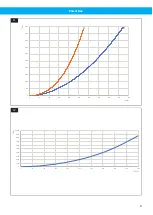
Pressure drop shown is for arm only. To get the
total pressure drop with extraction arm and
Power Box add the values from
4 Installation
WARNING! Risk of personal injury
The Power Box must be mounted according to
the installation instructions.
See
to
.
NOTE!
The pictures may vary due to different types.
•
shows two vacuum outputs (A) female, dia-
meter 38 mm with swivel function and the sliding
valves (B) with on/off function. The sliding valves al-
low machines to be constantly connected to the va-
cuum outputs.
•
show connections and Out-
puts. Connect the rubber hose with the hose clips. In
order to prevent the connection from sliding apart
from the hose clips, A must be located on the correct
side of the pipe’s “flange” B. The tightening torque
of the hose clips must be 6-8 Nm.
NOTE!
only shows the connection to an in-
coming pipe with a “flange” (equivalent to
the Power Box).
Connect the control signal cable,
fan control via the dampers is required.
•
which two are adjustable (A) and one has a none ad-
justable feed pressure (B). These are complemen-
ted with connections suitable for the purpose. The
output air pressure (A) is adjusted via the lever (C) in
and is shown on the manometer (D).
Connecting: First, choose suitable connections for
the outputs. Then connect the ½” hose to the com-
pressed air supply, max 10 Bar.
•
and
show the power supply (only
on some types).
Information about voltage/current is on the sock-
ets,
B, is 1-phase 220V. All the electrical cables should
be connected to the same power source (to avoid
potential differences). Cables belong to sockets ac-
cording to
and
the groove (A) using tie-wraps,
WARNING! Risk of personal injury
• The electrical installation must be done by
an authorized electrician.
• Electrical sockets and cables vary depend-
ing on the type. Pay attention to any na-
tional or local standards.
• The protective bonding circuits' continuity
should be checked after the installation.
Colour scheme, electrical in-
stallation:
IEC
Protective ground (PE)
Green/yellow
striped
Neutral (N)
Blue
1 phase (L) / 3 phase (L1)
Brown
3 phase (L2)
Black
3 phase (L3)
Grey
5 Maintenance
WARNING! Risk of personal injury
Never carry out any service work, mechanic-
al or electrical, without first disconnecting the
power supply and the compressed air supply.
Inspect the Power Box twice a year as follows:
• Check the bracket/mounting/leakage.
• Check the electrical and compressed air connec-
tions.
• Check the couplings and valves regarding clearance
and wear.
• Check for damage/wear to hoses and cables.
6 Spare Parts
CAUTION! Risk of equipment damage
Use only N
$
e
$
d
$
e
$
r
$
m
$
a
$
n
$
original spare parts and ac-
cessories.
Contact your nearest authorized distributor or
N
$
e
$
d
$
e
$
r
$
m
$
a
$
n
$
for advice on technical service or
if you require help with spare parts. See also
w
$
w
$
w
$
.
$
n
$
e
$
d
$
e
$
r
$
m
$
a
$
n
$
.
$
c
$
o
$
m
$
.
6.1 Ordering spare parts
When ordering spare parts always state the following:
• The part number and control number (see the
product identification plate).
• Detail number and name of the spare part (see
w
$
w
$
w
$
.
$
n
$
e
$
d
$
e
$
r
$
m
$
a
$
n
$
.
$
c
$
o
$
m
$
/
$
e
$
n
$
/
$
s
$
e
$
r
$
v
$
i
$
c
$
e
$
/
$
s
$
p
$
a
$
r
$
e
$
-
$
p
$
a
$
r
$
t
$
-
$
s
$
e
$
a
$
r
$
c
$
h
$
).
• Quantity of the parts required.
12
Summary of Contents for Power Box
Page 7: ...Power Box Figures 1 2 3 4 7 ...
Page 8: ...Power Box 5 6 7 8 9 10 8 ...
Page 44: ...www nederman com ...


