FlexFilter
EN
4 Installation
FlexFilter with standard legs is delivered firmly
screwed onto a transport pallet. For the lowest trans-
port height, and a low centre of gravity, it is shipped
upside down. The dust collecting bin is delivered on
a separate pallet. See
1
Loosen 4 screws (on each side), see
.
2
Turn the FlexFilter as per
al position a catch will lock,
be released by pressing before lifting into an up-
right position.
3
Lift slowly and ensure the catch locks in the up-
right position. Secure with the 8 screws as per
.
4
shows the FlexFilter ready for removal
from the transport pallet. Bolt the FlexFilter onto
its foundation.
NOTE!
The distance from the wall behind the Flex-
Filter should be at least 800 mm (31.5”) to en-
able tilting when replacing the filter package,
see
. If the FlexFilter can not be tilted
there must be at least 1 m of the free area
above it to enable convenient replacement of
filters.
4.1 Site
The FlexFilter can be placed indoors or outdoors. The
foundation should be level and hard. If sited outdoors,
weatherproofing under a roof is recommended. In
case of high humidity (of the air being cleaned) the
FlexFilter should not be exposed to freezing temper-
atures.
The distance from the vacuum unit should be less
than 25 m.
4.2 Connections
For calculations of pressure drop, see
.
shows normal connections. The compressed
air must be dry and clean. It can be supplied from the
compressed air filter serving the vacuum unit. The fig-
ure indicates suitable pressure. Consumption of com-
pressed air is very small. Compressed air cylinders in
the vacuum unit and on the dust collectors are operat-
ing only a few times per hour. Any small single-phase
air compressor may be used if centrally distributed air
is not available.
Twin RF models must have parallel inlet and outlet fit-
tings as shown in
are included in the shipment. (Twin models without
RF function can also be fitted this way, but the pipes
are not included in the package.)
The cabinet is prepared for filter cleaning using a Ne-
derman control unit. It is therefore not necessary
to use external control equipment. For connecting,
please refer to the manual of the control unit.
If the FlexFilter is provided with a fire alarm, the tem-
perature probe (see
) can be connected to
the starting equipment in such a way that the install-
ation will stop if the probe gives an alarm indicating
excessive temperature. As an alternative, the probe
can be connected to the main control computer in a
control room. In this case, which is recommended, the
control computer shall stop the unit by remote control
and also issue the desired type of fire alarm. The tem-
perature probe should be supplied from the control
computer by maximum 24V AC/DC and maximum cur-
rent 1 A. Please refer to the manual of the control unit.
If the FlexFilter is fitted with a BLI (Bin Level Indicator)
and/or a a DPS filter alarm (Different Pressure Switch)
they can be connected to a monitor. Nederman control
units are prepared for this. Please refer to the manual
of the control unit.
4.3 Settings
The manuals for the Nederman control units indicate
how to set intervals for the options of the FlexFilter.
5 Using FlexFilter
5.1 Initial start-up
This refers to a start of a complete vacuum installation
including vacuum units, starters, control units, dust
collectors and vacuum valves at work sites.
No special measures need to be taken with FlexFil-
ter dust collectors other than checking there is no
leakage and that controls units and accessories, if in-
stalled, work properly.
• Press the manual filter cleaning button on the con-
trol unit to check that filter cleaning works. A dis-
tinct change in sound reveals the function. The va-
cuum unit should be in operation producing vacuum,
in other words, it must not be idling.
If the fire alarm has been installed its function should
be checked. Disconnect one of the leads to the
thermal fuse (inserted in a holder on the top module).
This breaks the circuit and the vacuum unit should
stop. Depending on the wiring, an alarm may also be
triggered. See also
6 Maintenance
before carrying out mainten-
ance.
Installation, repair and maintenance work is to be car-
ried out by qualified personnel.
22
Summary of Contents for FlexFilter
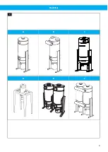
Page 8: ...FlexFilter Figures A B C D 1 A B C D 2 4 3 A B D 5 A B C 6 A B C 7 A B C D F G H A B C F G 1 8...
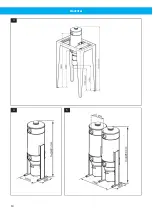
Page 9: ...FlexFilter A B C D E F 2 9...
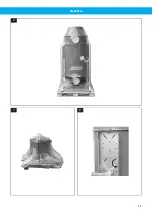
Page 10: ...FlexFilter 3 4 5 10...
Page 11: ...FlexFilter 6 7 8 11...
Page 12: ...FlexFilter 9 10 11 12 12...
Page 14: ...FlexFilter Min 2100mm 83 19 B A C 20 21 b a c A B 22 14...
Page 16: ...FlexFilter 25 16...
Page 152: ...www nederman com...


