background image

73                                                                 


                NED 

XCM2080SAT4

/

XCM2040SAT4                


UME-0006-04 

8.6.4 Intelligence 

Operating it in the

Intelligence

tab. 


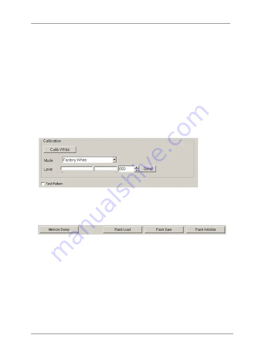
  < Calibration > 


Calib White

 : 

    Acquisition of white data and saving the calibration data to camera

’s flash  

memory. 


Mode 

/

 Level

 : 

    First, choose the mode from the drop-down-list-box. 

Next, set a value with the slider, the edit-box or the spin-button. Then, click 
“Send” button. 


Test Pattern

 : 

    ON/OFF of the test pattern output is switched clicking the check box.


8.6.5 Memory in camera 


Memory Dump

 : 

    Read the data from the camera

’s work memory. 


Flash Load

 : 

    Loading the data from the camera

’s flash memory. 


Flash Save

 : 

    Saving the data in the camera

’s flash memory. 


Flash Initialize

 : 

    Initializing the camera

’s flash memory with the factory standard data. 

Note: 

It takes a while to save and initialize.


Summary of Contents for XCM2040SAT4

Page 1: ...User s Manual Line Scan Camera Type XCM2080SAT4 XCM2040SAT4 NIPPON ELECTRO SENSORY DEVICES CORPORATION...

Page 2: ...e EU This equipment has been tested and found to comply with the essential requirements of the EMC Directive 2004 108 EC based on the following specifications applied EU Harmonised Standards EN55011 2...

Page 3: ...otherwise specified to do so in this manual When hands are wet avoid handling this product and do not touch any of the connection cable pins or other metallic components Do not operate this product in...

Page 4: ...a window Be careful not to scratch the glass Use of non infrared lighting such as a fluorescent lamp is recommended If halogen lighting is employed always install an infrared filter into your system c...

Page 5: ...sponsibility for any incidental damages loss of corporate profits interruption of business etc resulting form use or non use of this product The manufacturer assumes no responsibility for damages resu...

Page 6: ...y 24 4 Camera Control 25 4 1 Flow of Camera Control 25 4 1 1 Command Overview 25 4 1 2 Camera Receiving Message PC Sending Command 25 4 1 3 Camera Sending Message PC Receiving Message 26 4 1 4 Camera...

Page 7: ...etting 41 4 9 2 External Trigger Exposure Mode External trigger edge 42 4 9 3 External Trigger Exposure Mode Trigger Level 43 4 10 Setting Offset 44 4 11 Setting Gain 45 4 12 Pixel Correction 46 4 12...

Page 8: ...ntents of communication 68 8 5 6 Export Parameters to text file 69 8 5 7 Import Parameters from text file 69 8 6 Control 70 8 6 1 Gains and Offsets 70 8 6 2 Clock Integration 71 8 6 3 Exposure mode Tr...

Page 9: ...ct the difference between bits and shading 1 2 Application Inspection of Transparent panels and PCBs Visual inspection of high speed moving objects Flat panel display inspection Inspection of glass an...

Page 10: ...1 3 Image Sensor The camera adopts a CMOS sensor with the maximum data rate of 320MHz XCM2080SAT4 160MHZ XCM2040SAT4 to acquire high quality images and highly sensitive Both of the pixel sizes are 14...

Page 11: ...e Sequencer Clock External trigger OS1 1 512 OS2 513 1024 OS3 1025 1536 OS4 1537 2048 PD 512pixels CDS PGA A D C A D C MUX CDS PGA SPI PD 512pixels CDS PGA A D C A D C MUX CDS PGA SPI PD 512pixels CDS...

Page 12: ...vity V lx s typically Minimum Gain Pixel Correction Initial Value Daylight Fluorescent Light 50 Visible Area 400 700nm Analog 5V Conversion Sensitivity Gain Adjustable Range Analog Amplifier Digital A...

Page 13: ...mable Exposure Control 4 Scan Direction Switching Note 1 DN Digital Number 8bit 0 255 10bit 0 1023 2 Measurements were made at room temperature and daylight fluorescent light The spectral responsivity...

Page 14: ...Use the M4 screw holes 4 at the front 8 at the side to set the camera Or use the 1 4 20UNC screw hole for a tripod 1 place at bottom If using the front panel M4 mounting holes 4 places at front 8 plac...

Page 15: ...RY DEVICES CORP MADE IN JAPAN NIPPON ELECTRO SENSORY DEVICES CORP 68 100 60 73 5 32 59 1 7 unit mm 1 1 4 20UNC DEEP 6 1st Pixel 2048 4 M4 DEEP 6 TOP BOTTOM 4 M4 DEEP 6 BOTTOM SIDE 4 M4 DEEP 6 FRONT 40...

Page 16: ...E IN JAPAN NIPPON ELECTRO SENSORY DEVICES CORP 39 100 60 44 5 3 59 unit mm 1 1 4 20UNC DEEP 6 4 M4 DEEP 6 TOP BOTTOM 4 M4 DEEP 6 BOTTOM SIDE 4 M4 DEEP 6 FRONT 40 5 74 18 64 indicator 5 40 50 Power Con...

Page 17: ...posure time and quantities of light after examining which element the customer values enough 2 Keep these guidelines in mind when setting up your light source LED light sources are relatively inexpens...

Page 18: ...3 Use asymmetric Camera Link cables and connect the camera with the connector labeled as Camera side 4 There are two connectors in for Medium Configuration of Camera Link please after confirming the...

Page 19: ...The following table shows values being calculated in accordance with the Camera Link Specification 2007 Version1 2 using a typical cable 14B26 SZLB xxx 0LC from 3M and frame grabber board Solios from...

Page 20: ...dicator The layout of input output connecters and the LED indicator are as follows Figure 3 2 1 Input Output Connectors and Indicator indicator Power Connector HIROSE HR10A 4P CameraLink Connector MDR...

Page 21: ...00 100 100 SerTFG SerTC CC1 CC2 CC3 CC4 26 pin MDR Connector X1 X0 X2 X3 XClk SerTFG SerTC CC1 CC2 CC3 CC4 LVDS_DRIVER NS DS90CR287MTD equivalent LVDS_DRIVER RECEIVER NS DS90LV019TM equivalent LVDS_RE...

Page 22: ...H or L even if not used 3 Set the LVDS Channel Link receiver side to 100 ohm termination Figure 3 3 2 Circuit of LVDS The camera has 26 pin MDR connectors for control signals of Camera Link data sign...

Page 23: ...3 100 terminated 11 CC3 24 CC3 IN 11 100 terminated 24 100 terminated 12 CC4 25 CC4 IN 12 100 terminated 25 100 terminated 13 Inner Shield 26 Inner Shield 13 Inner Shield 26 Inner Shield Explanation o...

Page 24: ...es 1 When selecting a power source choose one with the capacity to allow for inrush current 15W or more recommended 2 Insert the cable plug securely until it locks into position This is to prevent the...

Page 25: ...erview The serial interface uses a simple ASCII based command Communication begins when the computer sends control commands to the camera The camera receives and interprets the computer commands and t...

Page 26: ...a readout value CR Separated text 0 x 0D EOT Send command all text end text 0 x 04 Table 4 1 3 1 Error Messages Camera Response Meaning OK Camera executed command CMD ERR Command is not valid CMD OVR...

Page 27: ...2767 6 7 3276 7 s XCM2080SAT4 13 4 6553 4 s XCM2040SAT4 Output Signal Setting voa 0 1 0 2 8bit 10bit 2048 pixel 4Tap 1024 pixel 2Tap 2048 pixel 2Tap Test Pattern tpn 0 1 OFF ON Pixel Correction Settin...

Page 28: ...e inm 0 Free Run Programmable Exposure Time int 2 1974 98 7 s XCM2080SAT4 197 4 s XCM2040SAT4 Output Signal Setting voa 0 0 8bit 2048pixel 4Tap Test Pattern tpn 0 OFF Pixel Correction Setting shc 1 51...

Page 29: ...33 OK CR gdx 255 CR EOT 4 2 3 Setting Digital Offset Sets digital offset 15 to 15 1DN step at 8bit 60 to 60 4DN step at 10bit Format S2 CMD VAL1 CR Format R1 R CR SB CR EOT CMD odx VAL 15 to 15 Examp...

Page 30: ...ulation of the exposure time 4 2 6 Setting Output Signals Setting Data Format Sets the data format of output signals Format S3 CMD VAL1 VAL2 CR Format R1 R CR SB CR EOT CMD voa VAL1 0 1 0 8bit 1 10bit...

Page 31: ...ction Sets pixel correction Format S3 CMD VAL1 VAL2 CR FormatR1 R CR SB CR EOT CMD shc VAL1 0 1 2 0 Correction OFF 1 Factory correction data ON 2 User correction target value ON VAL2 0 to 1023 Setting...

Page 32: ...o the factory default Format S1 CMD CR Format R2 R CR MEM CR SB CR EOT CMD rst Example rst CR OKCR Type XCM2080SAT4 CR Ver 1 00_0x8012 CR Serial 123456 CR Sensor 12 CR Background Offset 3 CR Latter Ha...

Page 33: ...R Type XCM2080SAT4 CR Ver 1 00_0x8012 CR Serial 123456 CR Sensor 12 CR Background Offset 3 CR Latter Harf of Tap Order 0 CR gax 1 CR gdx 0 CR odx 0 CR inm 0 CR int 2 1974 CR voa 0 0 CR tpn 0 CR shc 1...

Page 34: ...ent camera settings Format S1 CMD CR Format R2 R CR MEM CR SB CR EOT CMD sta Example sta CR OK CR Type XCM2080SAT4 CR Ver 1 00_0x8012 CR Serial 123456 CR Sensor 12 CR Background Offset 3 CR Latter Har...

Page 35: ...n Figure 4 3 1 Internal Circuit Configuration Block of Camera Sequencer Clock External trigger CLISBee CMOS Image Sensor Flash Memory FPGA Driver Indicator green Receiver Driver Receiver LVAL FVAL DVA...

Page 36: ...lly ending 1 The camera hardware initializes The indicator LED green blinks 2 Reads out the latest camera settings from the flash memory User settings if any or factory default settings 3 Set up the c...

Page 37: ...n the factory is shipped 3 If the camera power is disconnected while rewriting the memory the whole data saved in the memory will be deleted 4 As it takes several seconds to rewrite the memory do not...

Page 38: ...cation Settings Parameter Items Setup Value Communication Speed Baud rate 9600bps Data Length 8bit Parity Bit None Stop bit 1bit Flow Control None 4 8 Video Output Format The camera outputs 8 bit or 1...

Page 39: ...25 1026 1027 1028 1535 1536 1537 1538 buffer 512pixel buffer 512pixel buffer 512pixel buffer 512pixel TAP1 1 3 1021 1023 TAP2 2 4 1022 1024 TAP3 2047 2045 1027 1025 TAP4 2048 2046 1028 1026 1021 1022...

Page 40: ...4Pixel XCLK DVAL LVAL 1 2 3 4 509 510 511 512 1 3 5 7 2041 2043 2045 2047 2 4 6 8 2042 2044 2046 2048 Tap1 Tap2 2Tap 2048Pixel XCLK DVAL LVAL 1 2 3 4 1021 1022 1023 1024 Invalid Invalid Invalid Invali...

Page 41: ...mable parameters exposure time and readout time Table 4 9 1 1 Programmable Exposure Time Item symbol XCM2080SAT4 XCM2040SAT4 Programmable exposure time P 6 7 3276 7 4TAP 13 4 3276 7 2TAP 13 4 6553 4 4...

Page 42: ...de Trigger Edge the exposure time is determined by the setting for the line period parameter each exposure starts with the rising edge and the line period is determined by the time from rising edge to...

Page 43: ...with the rising edge and the line period is determined by high trigger pulse time The range of programmable exposure time the timing chart of the exposure and the readout are shown below Table 4 9 3 1...

Page 44: ...f 60 60 DN when 10bit is output 15 15 DN when 8bit is output It sets by command odx Figure 4 10 1 Saturation Exposure and Dark Current Output Note 1 Adjust amount of offset in accordance with the requ...

Page 45: ...n can be changed by sending the gdx command Figure 4 11 1 Gain Adjustment Gain Sensitivity of digital gain x1 pixel correction default factory white correction data is shown below Table 4 11 1 Gain Se...

Page 46: ...t data of each pixel at perfectly dark factory correction Cal_wh Output data of each pixel in uniform illumination factory correction or in taking a picture of subject for correction user white correc...

Page 47: ...ormity of the object 2 Send the wht CR command through serial communication 3 Confirm that the camera returns OK and wht Thus arbitrary white correction data is saved and loaded to the camera 4 Send t...

Page 48: ...proper timing and connections between the camera and the frame grabber board The test pattern of XCM2080SAT4 XCM2040SAT4 is below Figure 4 13 1 Test Pattern of 10bit 2048 Pixels Figure 4 13 2 Test Im...

Page 49: ...040SAT4 UME 0006 04 Figure 4 13 3 Test Pattern of 8bit 2048 Pixels Figure 4 13 4 Test Image of 8bit 2048 Pixels It increases in increments of 1DN to 1023DN in order from the first pixel 0DN This patte...

Page 50: ...040SAT4 UME 0006 04 Figure 4 13 5 Test Pattern of 8bit 1024 Pixels Figure 4 13 6 Test Image of 8bit 1024 Pixels It increases in increments of 1DN to 255DN in order from the first pixel 0DN This patter...

Page 51: ...XCM2080SAT4 XCM2040SAT4 UME 0006 04 Figure 4 13 7 Test Pattern of 10bit 1024 Pixels Figure 4 13 8 Test Image of 10bit 1024 Pixels It increases in increments of 1DN to 1023DN in order from the first pi...

Page 52: ...Link cable If one of the connectors says Camera side connect it to the camera Figure 5 1 2 Connection Direction of Camera Cable Confirm the connection with the Camera Link cable and frame grabber The...

Page 53: ...using the camera control utility Launch CLISBeeCtrl set COM port and connect Click Memory Dump and wait for the response Figure 5 2 1 Confirmation of Connection 2 Set a trigger mode and a video outpu...

Page 54: ...4 NED XCM2080SAT4 XCM2040SAT4 UME 0006 04 3 Capture images using a camera interface board utility In case of Matrox s Solios it is convenient to use Intellicam Figure 5 2 3 Solios Intellicam dcf Windo...

Page 55: ...t the power cable and Camera Link cables are connected to the camera correctly Camera Link cables come under the influence of noise when the cables are laid near a light source inverter line or a powe...

Page 56: ...he CMOS sensor window is part of the optical path and should be handled like other optical components with care If you use the camera in a dusty area prepare a dust proof enclosure Dust can obscure pi...

Page 57: ...the power source meets the specified voltage The capacity of the power source is enough Connect the camera and the frame grabber board with camera cables After being energized set up the frame grabbe...

Page 58: ...e images are too dark try to increase the light intensity and vice versa No image at the full aperture The optical axes of the camera and the image sensor are aligned Check the compatibility between t...

Page 59: ...has been used for 3 or more years or the ambient temperature is higher than room temperature Check the condition of the power supply The camera and or cables are used in a moving environment attached...

Page 60: ...cordance with the transmission rate The cables should not be too long to avoid the noise disturbance The power source has no fluctuation in voltage and is not deteriorated Use a stable power supply Th...

Page 61: ...is larger than the rating The camera will become hotter than the ambient temperature while in operation because of self heating Allow sufficient air circulation around the camera to give it the longe...

Page 62: ...the nickname for XCM series camera 8 2 System Requirements PC PC AT compatible Operating System Microsoft Windows 2000 or XP Windows Vista not confirmed Free disk space 1 2MB It may fluctuate with the...

Page 63: ...and Double click the CLISBeeCtrl exe It is possible to switch the page by clicking each tab under the window Buttons in the tool bar have the following functions A Exporting parameters in the text fil...

Page 64: ...2 1 Selecting interface 1 Click button D Select the interface in Drop down list box Click Setting button to set the interface See 8 5 2 2 and 8 5 2 3 Click OK button Click Cancel button when stopping...

Page 65: ...differs to the camera to connect is shown follow there 1 Port Select connecting port 2 Bits per Second 9600 3 Data bits 8 4 Parity None 5 Stop bits 1 6 Flow control None Note Other parameters are not...

Page 66: ...connect into Serial Index column Click OK button Click Cancel button when stopping setup Note The camera can be used without this operation after it has been set up correctly Note DLL for Camera Link...

Page 67: ...maximum time from sending a command to receiving the first data Next Receive The maximum time between a letter and the next one Send The maximum time until finishing sending a command Click OK button...

Page 68: ...AT4 XCM2040SAT4 UME 0006 04 8 5 4 Disconnect and end program Click button C Then click X button in the upper right of the window 8 5 5 Check of the contents of communication Click Console tag near the...

Page 69: ...Click button A Input file name and click Save button Present setting value of each control is saved by text format 8 5 7 Import Parameters from text file Select menu File Text Load Input file name and...

Page 70: ...ignal will be sent to the camera every time you make a selection from the menu in the drop down list box Note This camera does not use Analog 2 Digital Set a value with the slider the edit box or the...

Page 71: ...x or the spin button Then click Send button Padding Read Only Scanrate Counter automatic setting The Counter value of Clock Dividing and Padding is calculated and set from the present value when the s...

Page 72: ...l The signal will be sent to the camera every time you make a selection from the menu in the drop down list box Video output Select the number of the output bit and the output block The signal will be...

Page 73: ...ue with the slider the edit box or the spin button Then click Send button Test Pattern ON OFF of the test pattern output is switched clicking the check box 8 6 5 Memory in camera Memory Dump Read the...

Page 74: ...rsion software See 8 3 Install 8 8 How to Program Please refer sample programs in CLISBeeCtrl SampleProgram folder 8 9 Attention on use Reproducing and distributing without notice the part or all of t...

Page 75: ...y errors or omissions please notify your nearest NED representative 9 2 Contact for support Nippon Electro Sensory Devices Corporation Head Office 2 5 12 Itachibori Nishi ku Osaka 550 0012 Japan Phone...

Page 76: ...ch case please inform us of the status of the camera You can get the status by 1 executing the sta command or 2 clicking Memory Dump button when using CLISBeeCtrl The example of the camera status Sta...

Page 77: ...0006 04 Revision History Revision Number Date Changes 01 24 Mar 2010 Initial release 02 7 Jul 2010 Add directive on WEEE etc 03 10 Jun 2011 Add calculated value of maximum cable length 04 10 Oct 2012...

Reviews: