background image

USER MANUAL 2AMDI511IPVRDS

www.nectogroup.com

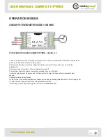
POTENTIOMETER WIRING 

2AMDI511IPVRDS

 - FIGURE N. 2

In order to activate this mode of control/operation just connect a linear potentiometer of 100 Kohm between the D+

and D- inputs and disconnect the remaining inputs.

By default, the dimming curve follows a logarithmic trend proportional to the resistance value set by the

potentiometer.

A resistance value of less than 5 Kohm is interpreted as load off.

The maximum brightness value is reached by exceeding the value of 95 Kohm.

In case the potentiometer is disconnected, the dimmer sets the output to the saved level (see preset level

change).

The preset value is zero by default.

On the first run in this mode it could be necessary to set the input to a value greater than 50% (55K or higher on DD

+ input) in order to configure the dimmer to the potentiometer mode.

*This setting can be configured through the interface cod. 2AMIN4030000N 

OPERATION MODES

LINEAR POTENTIOMETER MODE 100KOHM

pag|5

Summary of Contents for 2AMDI511IPVRDS

Page 1: ...MANUAL 2AMDI511IPVRDS SUBJECT INDEX DESCRIPTION TECHNICAL SPECIFICATION DEVICE POWER SUPPLY AND CONNECTION TO THE LED MODULE OPERATION MODES LINEAR POTENTIOMETER MODE 100KOHM MODE 0 10V 1 10V PASSIVE...

Page 2: ...s 40x100x24 45 mm Reverse polarity protection Open circuit protection Surge voltage protection Over temperature protection Short circuit protection PULSANTE N O ISOLATO DIMMER MONOCANALE MULTIPROTOCOL...

Page 3: ...MAX OUTPUT CURRENT n OUTPUT CHANNELS MAX OUTPUT POWER CONTROL INPUTS CASE DIM 2AMDI511IPVRDS 8 53V DC DA 170mA A 1050mA 1 54 6W A 52V DC INSULATED PUSH BUTTON X1 DALI X1 LINEAR POTENTIOMETER 100K X1...

Page 4: ...G 1 through the DC IN and terminals In case the power supply polarity is inverted no damage will be caused to the device The LED LED PWR positioned on the circuit board indicates the presence of power...

Page 5: ...ce value of less than 5 Kohm is interpreted as load off The maximum brightness value is reached by exceeding the value of 95 Kohm In case the potentiometer is disconnected the dimmer sets the output t...

Page 6: ...fault the dimming curve follows a logarithmic trend proportional to the control voltage A voltage value of less than 1V is interpreted as load off In case the 0 10V 1 10V signal is disconnected the di...

Page 7: ...n N O No polarization is needed for the input signal The maximum current absorbed by the PUSH interface is about 2mA The dimmer saves the output position in order to restore the set level in case of p...

Page 8: ...the POWER ON LEVEL mode set through DALI bus The maximum current absorbed by the DALI bus is about 2mA Below you can find the implemented standard commands DIRECT ARC POWER OFF UP DOWN STEP UP STEP DO...

Page 9: ...NUMBER QUERY DEVICE TYPE QUERY PHISICAL MINIMUM LEVEL QUERY POWER FAILURE QUERY CONTENT DTR1 QUERY CONTENT DTR2 QUERY ACTUAL LEVEL QUERY MAX LEVEL QUERY MIN LEVEL QUERY POWER ON LEVEL QUERY SYSTEM FA...

Page 10: ...OFF OFF OFF OFF OFF OFF OFF ON OFF OFF 235 mA OFF ON OFF OFF OFF OFF OFF OFF OFF OFF OFF ON OFF ON 250 mA OFF ON OFF OFF OFF OFF OFF OFF OFF OFF OFF ON ON OFF 260 mA OFF ON OFF OFF OFF OFF OFF OFF OF...

Page 11: ...OFF ON OFF 748 mA OFF ON OFF OFF OFF OFF OFF OFF ON OFF ON OFF ON ON 761 mA OFF ON OFF OFF OFF OFF OFF OFF ON OFF ON ON OFF OFF 775 mA OFF ON OFF OFF OFF OFF OFF OFF ON OFF ON ON OFF ON 788 mA OFF ON...

Reviews: