Necta Snakky 6-27R/F Service Manual Download Page 19

NECTA SPA TECHNICAL MANUAL 

“ Snakky “ 

Manual  

Snakky


19

 / 23 

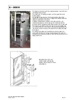
10 – TROUBLESHOOTING  

Problem 

(and/or indication on the 

display)


Possible cause


Solution


The display indicates 

the message: 

“Compressor” 


If the compressor runs for 24 hours 

consecutively without the cabinet reaching 
the temperature set via the SW, the machine 

is locked and the selection disabled. 
The following could be the cause: 

Lack of gas in the refrigerating circuit. 
Failure to the evaporator’s electric fan. 
Failure to the condenser’s electric fan or PTC 

triggered. 
Clogged rear and/or side grille 

Failed probe (in this case the message “probe 
failure” will be displayed) 

Normally two to four hours are required to 

reach the operating temperature (according to 
the load). A longer time means that there is a 

malfunction: check for any small leaks in the 
refrigerating gas circuit; if necessary repair the 

leak and charge with the correct dose of gas. 
Check that the electric fans work correctly. 
Check for the correct cooling airflow inside the 

refrigerated box. In the case of failure to 
components, replace with original parts. 

The display indicates 

the message 

“Coin mechanism” 


If the CPU for more than 30 seconds does 
not receive communication impulses from an 

Executive serial coin mechanism, or 75 
seconds from a BDV serial coin mechanism, 

or if it receives an impulse for longer than 2 
seconds, the machine locks and the 

selections are disabled. 

Replace the coin mechanism with one that is 
certain to work and check the communication. 

Check connections. 
Check the CPU board, and if necessary replace 

with that is certain to work. 
Check that the 24 V DC power supply fuse is 

intact. 


The display indicates 

the message 

“RAM data” 


One or more areas of the RAM contain wrong 
data, which could change the operating 

default values. 
The machine will continue working, but some 

parameters could have been changed, with 
consequences to the general functioning - 

the RAM needs to be initialised as soon as 
possible to recover data from the EPROM. 


Initialise the CPU again. 
After initialising, all data settings will go back to 

the default settings; restore the customised 
data using the programmer or a PC. 

If, in spite of initialising, the malfunction 
persists, replace the CPU board with an already 

tested one that is certain to work. It the 
malfunction persists, replace the cables or 

check the suitability of connections. 
The machine was designed to comply with the 

EMC directive, but if located in an environment 
subject to high interference immunity problems 

could arise, therefore in the event of such 
interference persisting the vending machine 
should be moved to a different location. 

The display indicates 

the message 

“Probe” 


The temperature control probe in the 
refrigerated box is of the NTC type, with the 

internal resistance that changes as the 
temperature changes. 

If the probe is interrupted, the machine locks 
after 5 minutes from the failure and the 

selections are disabled (THE DISPLAY WILL 
INDICATE THE TEMPERATURE – 5 ° C) 

If there is a short-circuit in the probe, the 
machine locks after 60 minutes and the 
selections are disabled (THE DISPLAY WILL 

INDICATE THE TEMPE32° C) 

NB

: AFTER THE SENSOR FAILURE HAS BEEN 

DISPLAYED FOR TWO HOURS, A 
COMPRESSOR FAILURE WILL ALSO BE 

INDICATED. 

Check the internal resistance in the NTC probe 
using a digital multimeter: A resistance of 730 

ohm corresponds to a temperature of 30° C. 
A resistance of 2612 ohm corresponds to a 

temperature of 0° C (melting ice). 
Replace the probe with an original one; before 

installing the new one check that the internal 
resistance corresponds to the above 

parameters.  
Reset the failures by accessing the special 
function 

Summary of Contents for Snakky 6-27R/F

Page 1: ...TA SPA TECHNICAL MANUAL Snakky Manual Snakky 1 23 AFTER SALES SERVICE food snack SERVICE MANUAL SNAKKY BASIC TECHNICAL MANUAL THE CONTENTS OF THIS DOCUMENT ARE INTENDED FOR NECTA S AFTER SALES PERSONNEL by ...

Page 2: ... 11 12 Layout Models Electrical systems connections and configuration Release dispensing storage systems Wiring Power supply Cooling unit Cabinet Door Wiring diagrams Trouble shooting HACCP directive Use instructions Periodical cleaning and hygiene Page 3 Pages 4 5 6 7 8 9 Pages 10 11 Page 12 Page 13 Pages 14 15 Page 16 Page 16 Page 17 Pages 18 19 20 Page 21 Pages 22 23 Reference Description 1 Doo...

Page 3: ...sion is not approved by IMQ or that it is awaiting approval DESCRIPTION VARIABLES TRAYS Up to 6 max HEIGHT 0F TRAYS 96 mm min and up to 219 mm max PARTITIONS PER TRAY 2 triple 3 double 6 single PRICES PER TRAY One for each selection TIME BANDS Available for configuration PAYMENT SYSTEMS Serial EXE as standard feature MDB BDV with additional board VEND SYSTEMS With single and double spiral DIMENSIO...

Page 4: ...rations with indication of their position The examples shown below correspond to real layouts indicated on the side in any case there are many configurations options with simple and quick change operations see specific paragraph Snakky 6 27R F Snakky 6 30R I Snakky 6 32R F Snakky 6 33R E ...

Page 5: ... x 1 5 mm2 section HO5 V V F HO7 RN F Fitted with a fixed SCHUKO plug NOTE For UK there is a specific plug conforming to the standards in force which is adopted for that specific market In the event of replacement cables of exactly the same characteristics must be used Since the Snakky vending machine is approved by an electrical safety certification institute IMQ replacements with non original co...

Page 6: ...ARD CONNECTIONS SP push button card LCD display Board RS232 port Printer PC Programmer Transmitter photodiode card Phototransistor card Receiver NTC Probe Cooling unit control Cooling unit control Lamp control Grid 230 V 50 Hz Electric power supply Payment system connections Bord SUC J2 to the ratiomotors ...

Page 7: ...g the normal operation YELLOW LED It glows when 5 V DC is present in the board RED LED it glows when the software is reset program malfunction Minidip functions 1 4 19 Coin mechanism setting 2 3 By default set to OFF Minidips 1 8 16 Default configuration setting fixed to OFF Both will be eliminated in the near future thus since now the configuration is only via software setting The CPU board is ho...

Page 8: ...NECTA SPA TECHNICAL MANUAL Snakky Manual Snakky 8 23 TRAY CONNECTION WIRING DIAGRAM CONNECTOR Detail of spiral control ratiomotor To connector J2 SUC board ...

Page 9: ...T Receiver photo transistor card IP Sliding panel switch LCD LCD display card M1 6 Spiral control ratiomotors MDB Connector for coin mechanism with MDB protocol MUR Cooler unit MVT Electric fan NTC NTC probe for refrigerated box internal temperature monitoring and control RS 232 Serial port for PC printer and programmer connection RT Neon lamp ballast SOR Cooling unit control relay card SP Selecti...

Page 10: ...titions and the motors one two or three position trays can be used to dispense any products Different pitch spirals are available to be able to load 20 to 76 mm wide products In addition the spirals can have right and left pitch to be used in the case of two spirals in the same partition The rear position motor is fitted with a minidip permitting the inversion of the direction of rotation Example ...

Page 11: ...nt function start from the power supply unit FIG 2 All connections for the vending machine control start from the CPU board push buttons payment systems ratiomotors heating elements display FIG 3 The 230 V 50 Hz grid power supply is transformed by means of 24 V AC transformer TR then sent to the machine board that rectifies it to DC and sends it to the users through the actuations A relay card for...

Page 12: ... is protected with a main switch and two fuses on both phases It is also fitted with a noise suppressor The CPU boards controls also a relay card for the 230 V 50 Hz actuations Lamps cooling unit and electric fans The same box houses the ballasts for the neon lamps and all main fuses easily accessible from the outside with the door open Safety key Transformer Relay card Grid noise suppressor Conne...

Page 13: ...to the relay card that activates or deactivates the cooling unit operation The cooling unit is very compact and of the slide in type in any case it is designed to be extracted easily and quickly To access the cooling unit the last tray must be extracted then the anti theft grille and the dispensing compartment must be removed At this point the complete cooling unit can be extracted List of compone...

Page 14: ...f future scrapping of the machine the cabinet can be disassembled completely without any complications almost impossible in the case of cabinet injected with foam The base is made with varnished and welded sheet metal the feet are adjustable for perfect levelling and after removing the lower grille a trans pallet can be used to move the machine As optional feature supports are provided to be place...

Page 15: ... on its front panel the CPU board and the payment system compartment are fitted inside on the central wall The following are fitted on the front panel the main display the coin slot and the coin return button the selection keypad and the lock that as well as ensuring a three point lock it keeps the glass door closed The sliding compartment is protected by a safety switch that disconnects the 230 V...

Page 16: ...L MANUAL Snakky Manual Snakky 16 23 9 WIRING DIAGRAMS POWER SUPPLY AND LIGHTING DIAGRAM 1 2 1 2 power supply to EXE coin mechanisms 3 4 connector J14 24 V DC power supply card 5 6 7 in out connector J3 to board 3 4 5 6 7 ...

Page 17: ...NECTA SPA TECHNICAL MANUAL Snakky Manual Snakky 17 23 Wiring diagram of tray ratiomotor controls ...

Page 18: ...NECTA SPA TECHNICAL MANUAL Snakky Manual Snakky 18 23 Wiring diagram of CPU board connection See page 6 for connections ...

Page 19: ...ong data which could change the operating default values The machine will continue working but some parameters could have been changed with consequences to the general functioning the RAM needs to be initialised as soon as possible to recover data from the EPROM Initialise the CPU again After initialising all data settings will go back to the default settings restore the customised data using the ...

Page 20: ...correctly connected Check that the cables are efficient The machine does not start and the display is off The vending machine is protected against short circuits with two line fuses one on each phase with fuses on the secondary winding and on CPU board power supply see wiring diagram Check that the fuses are intact and if necessary replace First identify the cause of the blown fuses Check the powe...

Page 21: ...l manual for correct hygiene practices After cleaning do not touch the surface of any elements that may come into contact with food Wash your hands thoroughly preferably using disinfectant before starting any hygiene operations Use disposable sterile gloves Always use a clean cloth to wipe dry Keep the work area tidy Check that the product packages are intact and not damaged Use products within th...

Page 22: ... the trays and clean the inside of the refrigerated box check for the presence of insects FIG 1 FIG 2 Open the door and disconnect the machine form the power supply FIG 1 Clean the outside and inside of the glass front with suitable detergent Clean the inside of the trays with a cloth dampened with chlorine based detergents Wipe the dispensing compartment and the flap door with a clean cloth befor...

Page 23: ...the cooling unit FIG 3 thoroughly clean the internal base and make hygienic Remove all the dust from the fans and cooling unit condenser FIG 4 Clean and make hygienic the condensation tray FIG 4 Reinstall the cooling unit Reinsert into the operating position Clean the external parts especially the coin return compartment and the push buttons Reassemble all trays after cleaning the internal product...

Reviews: