background image

48

6. Maintenance

ME

NU

SELECT

LAMP

STATU

S

POW

ER

ON

/ST

AN

D B

Y

SO

UR

CE

AU

TO

 AD

J.

E

N

T

E

R

EX

IT

FO

C

U

S

ZOOM

Filter

This section describes the simple maintenance procedures you should follow to clean the filters and replace the lamp.

���

 Cleaning or Replacing the Filters

The air-filter sponge keeps dust and dirt from getting inside the projector and should be frequently cleaned. If the filter
is dirty or clogged, your projector may overheat.

NOTE: The message for filter cleaning will be displayed for one minute after the projector is turned on or off.
To cancel the message, press any button on the projector cabinet or the remote control.

CAUTION

Turn off the projector, turn off the main power switch and unplug the projector before replacing the filters.

Only clean the outside of the filter cover with a vacuum cleaner.

Do not attempt to operate the projector without the filter cover.

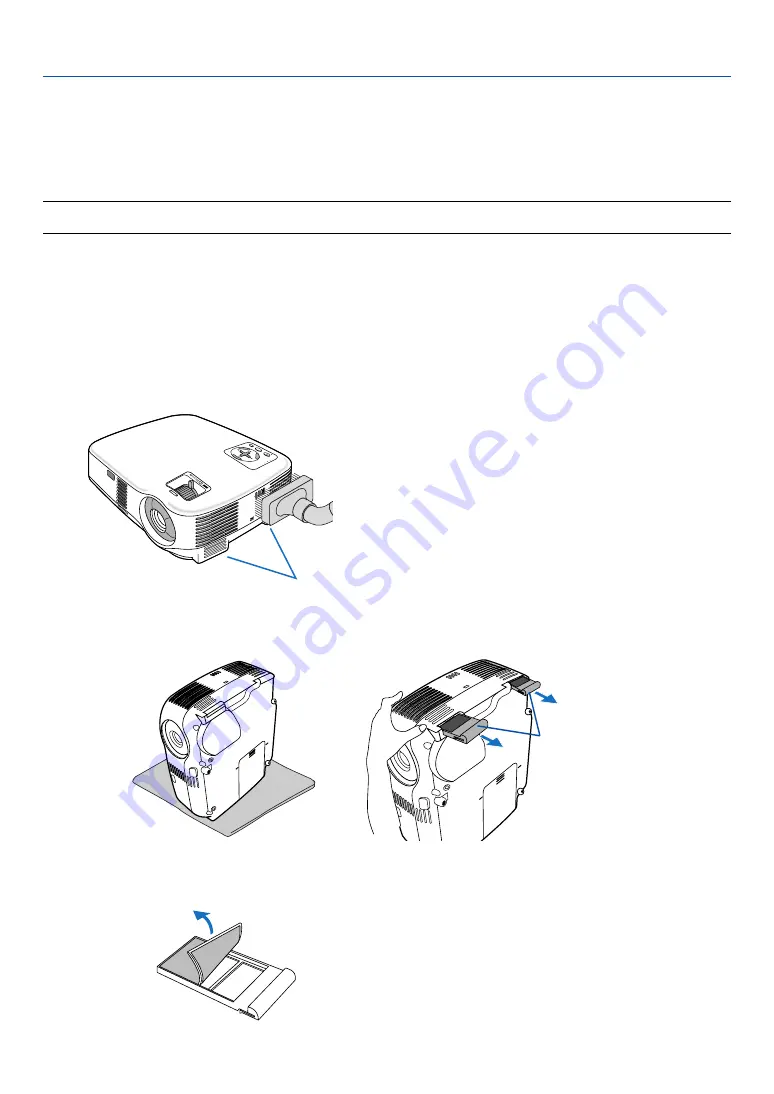
To clean the air-filter:

Vacuum the filter-through the filter cover.

To replace the filter (sponge):

1. Remove the filter cover by pushing down on the catch of the cover until you feel it detach.

Catch

2. Gently peel off the filter (sponge) and replace it with the new one.

Summary of Contents for VT700

Page 1: ...T700 User s Manual The projector s model name indicated on the projector s label is VT700 and VT700G respectively All two models are referred to as VT700 throughout the user s manual except some of the specifications pages ...

Page 2: ... Other product and company names mentioned in this user s manual may be the trademarks or registered trade marks of their respective holders NOTES 1 The contents of this user s manual may not be reprinted in part or whole without permission 2 The contents of this user s manual are subject to change without notice 3 Great care has been taken in the preparation of this user s manual however should y...

Page 3: ...DOC Compliance Notice for Canada only This Class B digital apparatus meets all requirements of the Canadian Interference Causing Equipment Regulations Machine Noise Information Regulation 3 GPSGV The highest sound pressure level is less than 70 dB A in accordance with EN ISO 7779 CAUTION Avoid displaying stationary images for a prolonged period of time Doing so can result in these images being tem...

Page 4: ...couraged to try to correct the interference by one or more of the following measures Reorient or relocate the receiving antenna Increase the separation between the equipment and receiver Connect the equipment into an outlet on a circuit different from that to which the receiver is connected Consult the dealer or an experienced radio TV technician for help For UK only In UK a BS approved power cabl...

Page 5: ...ting of the cap and possibly burning your hands due to the heat emitted from the light output Do not place any objects which are easily affected by heat in front of the projector lens or a projector exhaust vent Doing so could lead to the object melting or getting your hands burned from the heat that is emitted from the light output and exhaust Handle the power cable carefully A damaged or frayed ...

Page 6: ... regulations Lamp Replacement To replace the lamp follow all instructions provided on page 50 Be sure to replace the lamp when the message The lamp has reached the end of its usable life Please replace the lamp appears If you continue to use the lamp after the lamp has reached the end of its usable life the lamp bulb may shatter and pieces of glass may be scattered in the lamp case Do not touch th...

Page 7: ...ng Connections 11 Enabling the computer s external display 11 Connecting Your PC or Macintosh Computer 11 When Viewing a DVI Digital Signal 12 Using Two Analog COMPUTER Inputs Simultaneously 13 Connecting an External Monitor 14 Connecting Your DVD Player with Component Output 15 Connecting Your VCR or Laser Disc Player 16 Connecting the Supplied Power Cable 17 3 Projecting an Image Basic Operation...

Page 8: ...ions Functions Picture 39 Menu Descriptions Functions Image Options 40 Menu Descriptions Functions Setup 42 Menu Descriptions Functions Information 46 Menu Descriptions Functions Reset 47 6 Maintenance 48 Cleaning or Replacing the Filters 48 Cleaning the Cabinet and the Lens 49 Replacing the Lamp 50 7 Appendix 53 Troubleshooting 53 Specifications 56 Cabinet Dimensions 58 Pin Assignments of D Sub C...

Page 9: ... Introduction V O LU M E S V ID E O V ID E O L C LI C K E N TE R E X IT M E N U U P M A G N IF Y P A G E O F F P O W E R O N P IC M U T E D O W N M O U S E R C LI C K AU TO AD J LA M P M O D E C O M PU TE R A S P E C T H E LP F R E E Z E P IC T U R E 1 2 Remote control 7N900731 Batteries AAA 2 Carrying handle 24FT9651 Screw M4 2 24V00411 What s in the Box Make sure your box contains everything lis...

Page 10: ...ng down The fans stop 30 seconds after turning off the power from the remote control or cabinet control panel The projector can be put away immediately after the projector is powered down Also the main power of the projector can be turned off by pressing the main power switch or unplugging the power cable even during the cool down period after the projector is turned off DVI input connector DVI I ...

Page 11: ...ters AC Input Connect the supplied power cable s two pin plug here and plug the other end into an active wall outlet page 17 Main Power Switch When you plug the supplied power cable into an active wall outlet and turn on the Main Power the POWER indicator turns orange and the projector is in standby mode page 18 26 Remote sensor page 8 Terminal Panel page 6 Monaural Speaker 5W This security slot s...

Page 12: ...ng handle securely to the projector To attach the supplied carrying handle use a Phillips head screwdriver and the supplied two screws Place a soft cloth on the working surface before turning the projector over to prevent scratching the top cover Make sure that the carrying handle is attached with correct orientation as shown below CAUTION When carrying the projector by the carrying handle make su...

Page 13: ...E 4 7 8 3 1 2 9 10 5 6 1 LAMP Indicator page 50 53 2 STATUS Indicator page 53 3 POWER Indicator page 18 26 53 4 POWER Button ON STAND BY page 18 26 5 SOURCE Button page 20 6 AUTO ADJ Button page 25 7 MENU Button page 34 8 SELECT Volume Buttons Key stone Buttons page 23 25 9 ENTER Button 10 EXIT Button ...

Page 14: ...IO OUT Mini Jack Stereo Mini page 14 4 MONITOR OUT Connector Mini D Sub 15 Pin page 14 5 S VIDEO IN Connector Mini DIN 4 Pin page 16 6 VIDEO IN Connector RCA page 16 7 AUDIO Input Jacks L R RCA page 15 16 8 PC CONTROL PC CTRL Port DIN 8 Pin page 61 Use this port to connect a PC or control system This enables you to control the projector using serial communication protocol If you are writing your o...

Page 15: ...N MOUSE R CLICK COMPUTER ASPECT HELP FREEZE PICTURE S VIDEO VIDEO COMPUTER AUTO ADJ LAMP MODE 2 1 1 3 4 7 6 9 2 8 10 11 13 14 12 21 22 20 16 15 18 5 17 19 12 MOUSE R CLICK Button page 32 33 13 VIDEO Button page 20 14 S VIDEO Button page 20 15 COMPUTER 1 2 Button page 20 16 AUTO ADJ Button page 25 17 VOLUME Button page 25 18 LAMP MODE Button page 29 19 ASPECT Button page 40 20 PICTURE Button page 3...

Page 16: ...ver off 2 Install new batteries AAA Ensure that you have the batteries polarity aligned correctly The infrared signal operates by line of sight up to a distance of about 22 feet 7 m and within a 60 degree angle of the remote sensor on the projector cabinet The projector will not respond if there are objects between the remote control and the sensor or if strong light falls on the sensor Weak batte...

Page 17: ...easured diagonally when the projector is roughly 38 inches 1 0 m from the wall or screen The largest the image can be is 300 7 6 m when the projector is about 389 inches 9 9 m from the wall or screen 300 240 200 180 150 120 100 60 40 30 21 80 D i s t a n c e U n i t m i n c h Screen Size Unit cm inch Screen Size Lens center 609 6 W 457 2 H 240 W 180 H 487 7 W 365 8 H 192 W 144 H 406 4 W 304 8 H 16...

Page 18: ... 2490 2670 2970 3570 4470 5370 5970 6270 7170 8070 8970 inch 29 34 41 56 84 101 112 118 126 141 169 211 254 282 296 339 381 424 degree 10 3 10 2 10 1 10 1 10 0 10 0 10 0 10 0 10 0 10 0 10 0 10 0 10 0 10 0 9 9 9 9 9 9 degree 8 6 8 6 8 5 8 4 8 4 8 4 8 4 8 4 8 4 8 3 8 3 8 3 8 3 8 3 8 3 8 3 8 3 8 3 mm 730 870 1050 1410 2130 2560 2850 2990 3210 3570 4290 5370 6450 7170 7530 8610 9690 10770 Width Height...

Page 19: ...tosh Computer NOTE The COMPUTER 1 connector supports Plug Play DDC2 NOTE The projector is not compatible with video decoded outputs of the NEC ISS 6020 switcher NOTE An image may not be displayed correctly when a Video or S Video source is played back via a commercially available scan converter This is because the projector will process a video signal as a computer signal at the default setting In...

Page 20: ...f the signal cable has been disconnected and then re connected an image may not be correctly displayed Should this happen restart your PC NOTE Use a DVI cable or the one compliant with DDWG Digital Display Working Group DVI Digital Visual Interface revision 1 0 standard The DVI cable should be within 5 m 196 long Both single and dual types of DVI cable can be used The DVI DIGITAL connector accepts...

Page 21: ...es Desktop type or Macintosh Desktop type VGA signal cable not supplied DVI to VGA adapter supplied 2 Installation and Connections NOTE When the DVI to VGA adapter is not to be used for an extended period of time remove it from the projector Failure to do so may cause damage to the connector of the projector Using Two Analog COMPUTER Inputs Simultaneously If you need to use two analog COMPUTER inp...

Page 22: ...in connection is not possible The signal from the COMPUTER 2 IN connector cannot be output from the MONITOR OUT connector When the DVI Digital signal is selected no signals will be output from the MONITOR OUT connector AUDIO IN AUDIO OUT AUDIO IN MONITOR OUT COMP 1 COMPUTER 1 IN COMPUTER 2 DVI I IN AUDIO IN S VIDEO IN VIDEO IN PC CTRL L R MONITOR OUT AUDIO OUT VGA signal cable supplied VGA signal ...

Page 23: ...adio button NOTE Refer to your DVD player s owner s manual for more information about your DVD player s video output requirements AUDIO IN L R AUDIO OUT L R Component Y Cb Cr AUDIO OUT AUDIO IN MONITOR OUT COMP 1 COMPUTER 1 IN COMPUTER 2 DVI I IN AUDIO IN S VIDEO IN VIDEO IN PC CTRL L R COMPUTER 1 IN AUDIO IN DVD player Audio Equipment Audio cable not supplied 15 pin to RCA female 3 cable adapter ...

Page 24: ...o output requirements NOTE An image may not be displayed correctly when a Video or S Video source is played back in fast forward or fast rewind via a scan converter AUDIO IN L R AUDIO OUT L R VIDEO OUT S VIDEO VIDEO AUDIO OUT AUDIO IN MONITOR OUT COMP 1 COMPUTER 1 IN COMPUTER 2 DVI I IN AUDIO IN S VIDEO IN VIDEO IN PC CTRL L R VIDEO IN S VIDEO IN AUDIO IN S Video cable not supplied Video cable not...

Page 25: ...er the projector is turned off CAUTION Do not turn off the AC power by pressing the main power switch or by unplugging the power cable when the projector is powered on Doing so can cause damage to the projector TIP The projector can be turned off by either the main power switch or by unplugging the power cable during its cool down period after it is turned off using the remote control or via the p...

Page 26: ...er switch to the on position I The POWER indicator will light orange See the Power Indicator section page 53 2 Remove the lens cap 3 Press the POWER ON STAND BY button on the projector cabinet or the POWER ON button on the remote control for 1 second The POWER indicator will turn to green and the projector will become ready to use After you turn on your projector ensure that the computer or video ...

Page 27: ...to 5 minutes until the lamp lighting is stabilized When the Lamp mode is set to Eco the LAMP indicator will light green If one of the following things happens the projector will not turn on If the internal temperature of the projector is too high the projector detects abnormal high temperature In this condition the projector will not turn on to protect the internal system If this happens wait for ...

Page 28: ...ld the SOURCE button for a minimum of 2 seconds the projector will search for the next available input source Each time you press and hold the SOURCE button for a minimum of 2 seconds the input source will change as follows Computer1 Computer2 Digital Computer2 Analog Video S Video Computer1 TIP If no input signal is present the input will be skipped Using the Remote Control Press any one of the C...

Page 29: ...ff 2 Push and hold the Adjustable Tilt Foot Button on the front of the projector to extend the adjustable tilt foot 3 Lower the front of the projector to the desired height 4 Release the Adjustable Tilt Foot Button to lock the Adjustable tilt foot There is approximately 10 degrees up of adjustment for the front of the projector The rear foot height can be adjusted up to 0 4 inch 10 mm Rotate the r...

Page 30: ...R EXIT F O C U S Z O O M M E N U SE LE CT LA M P ST A TU S PO W ER ON S TA ND BY SO UR CE AU TO AD J ENTER EXIT F O C U S Zoom Use the ZOOM lever to adjust the image size on the screen Focus Use the FOCUS ring to obtain the best focus FOC US MEN U SELE CT LAM P STA TUS POW ER ON ST AND BY SOUR CE AUTO ADJ ENTER EXIT ZOO M ...

Page 31: ... be closed after a period of time NOTE When the menu is displayed the above operation is not available When the menu is displayed press the MENU button to close the menu and start the Keystone correction From the menu select Setup General Keystone The changes can be saved with Keystone Save page 42 Adjusting with the Remote Control 1 Press the MENU button The menu will be displayed 2 Press the SEL...

Page 32: ...ngle during projection The left and right horizontal keystone correction is not available Place the projector so that the lens surface is parallel to the screen The rear feet of the projector can be adjusted to level the projector NOTE Auto and Manual Keystone correction angle could be less than 30 degrees depending on the signal and or aspect ratios Using keystone correction can cause the image t...

Page 33: ...rease volume VOLUME L CLICK MOUSE R CLICK ASPECT HELP FREEZE PICTURE AUTO ADJ S VIDEO VIDEO COMPUTER LAMP MODE 1 2 NOTE Some signals may take time to display or may not be displayed correctly The Auto Adjust function does not work for component video and DVI digital signals If the Auto Adjust operation cannot optimize the RGB signal try to adjust Horizontal Vertical Position Clock and Phase manual...

Page 34: ...ned off by pressing the main power switch or by unplugging the power cable even during the cool down period after the projector is turned off NOTE Do not turn off the main power within 10 seconds of making adjustment or setting changes and closing the menu Doing so can cause loss of adjustments and settings Power On Fan running Standby Steady green light Blinking orange light Steady orange light P...

Page 35: ...vent the lens from damage 3 Projecting an Image Basic Operation NOTE When placing the projector in the soft case retract the tilt foot and the rear feet Failure to do so may case damage to the projector CAUTION Use caution when putting the projector in the soft case immediately after the projector has been operating The projector cabinet is hot MEN U SELEC T LAMP STAT US POW ER ON ST AND BY SOURC ...

Page 36: ... times NOTE The maximum magnification may be less than four times depending on the signal To do so 1 Press the MAGNIFY button to magnify the picture To move the magnified image use the SELECT or button 2 Press the MAGNIFY button to return the image to the original size 4 Convenient Features ENTER EXIT MENU UP MAGNIFY PAGE OFF POWER ON PIC MUTE DOWN ENTER EXIT MENU UP MAGNIFY PAGE OFF POWER ON PIC ...

Page 37: ...matically changes to Eco mode to protect the projector When the projector is in Eco mode the picture brightness decreases When the projector comes back to normal temperature the Lamp mode returns to Normal mode Thermometer symbol indicates the lamp mode is automatically set to Eco mode because the internal temperature is too high Preventing the Unauthorized Use of the Projector To enable the Secur...

Page 38: ...ake a note of your keyword The Confirm Keyword screen will be displayed NOTE Do not forget your keyword However if you forget your keyword NEC or your dealer will provide you with your Release Code upon proof of ownership See more information at the end of this section page 31 7 Type in the same combination of SELECT button and press the ENTER button The confirmation screen will be displayed 8 Sel...

Page 39: ...isable the Security function 1 Press the MENU button The menu will be displayed 2 Use the SELECT or button to select Setup and press the ENTER button 3 Use the SELECT or button to select Installation 4 Use the SELECT or button to select Security and press the SELECT button 5 Use the SELECT or button to select Off and press the ENTER button The keyword confirmation screen will be displayed 6 Type i...

Page 40: ...r settings When operating a computer via the remote mouse receiver When connecting using the USB terminal For PC the mouse receiver can only be used with a Windows 98 Me XP Windows 2000 Windows Vista or Mac OS X 10 0 0 or later operating system NOTE In SP1 or older version of Windows XP if the mouse cursor will not move correctly do the following Clear the Enhance pointer precision check box under...

Page 41: ...LICK or R CLICK button for 2 or 3 seconds then releasing the drag mode is set and the drag operation can be performed simply by pressing the SELECT button To drop the item press the MOUSE L CLICK or R CLICK button To cancel it press the MOUSE R CLICK or L CLICK button NOTE When you operate the computer using the SELECT or button with the menu displayed both the menu and the mouse pointer will be a...

Page 42: ...2 Press the SELECT or button on the remote control or the projector cabinet to highlight the menu for the item you want to adjust or set 3 Press the SELECT button or the ENTER button on the remote control or the projector cabinet to select a submenu or item ENTER EXIT UP MAGNIFY PAGE OFF POWER ON PIC MUTE DOWN MENU ENTER EXIT MENU UP MAGNIFY PAGE OFF POWER ON PIC MUTE DOWN ENTER EXIT MENU UP MAGNI...

Page 43: ...g items Solid triangle Solid triangle Indicates further choices are available A highlighted triangle indicates the item is active 1 Use the SELECT button to select the item 2 Use the SELECT buttons to highlight the item you want to set 3 Press the ENTER button The selected item will be displayed For Selecting items Radio button Radio button Use this round button to select an option in a dialog box...

Page 44: ...preset Solid triangle Indicates further choices are available A highlighted triangle indicates the item is active Tab Indicates a group of features in a dialog box Selecting on any tab brings its page to the front Radio button Use this round button to select an option in a dialog box Check mark Indicates the item is selected Slide bar Indicates settings or the direction of adjustment Key Lock symb...

Page 45: ...ski Türkçe Dansk Beep On Off On Installation Orientation Desktop Front Desktop Front Ceiling Rear Desktop Rear Ceiling Front Communication Speed 19200 4800 9600 19200 Control Panel Lock Off Off On Security Off Off On Menu Color Select Color Color Monochrome Menu Display Time Auto 45 sec Manual Auto 5 sec Auto 15sec Auto 45 sec Background Blue Blue Black Logo Filter Message 500 H Off 100 H 200 H 50...

Page 46: ...ync Composite Sync Sync on Green Sync on Video Sync Polarity Scan Type Interlace Non interlace Version Product Serial Number Firmware Data Reset Item Current Signal All Data Clear Lamp Hours Clear Filter Hours Signal Select Computer 1 RGB RGB Component RGB Component Component Computer 2 Analog RGB RGB Component RGB Component Component Video Auto Auto NTSC3 58 NTSC4 43 PAL PAL M PAL N PAL60 SECAM S...

Page 47: ... a brightly lit room Presentation Recommended for making a presentation using a PowerPoint file Video Recommended for standard video such as a TV program Movie Recommended for film based video such as a movie DVD or HDTV Graphic Recommended for viewing accurate colors in graphics sRGB Standard color values Selecting Gamma Correction Mode Gamma Correction Each mode is recommended for Dynamic Create...

Page 48: ...level of the image Brightness Adjusts the brightness level or the black level of the image Sharpness Controls the detail of the image for Video not valid for RGB Color Increases or decreases the color saturation level not valid for RGB Hue Varies the color level from green to blue The red level is used as reference This adjustment is only valid for Video and Component inputs not valid for RGB Rese...

Page 49: ...ottom of the black area NOTE This option is available only when Cinema is selected in Aspect Ratio Adjusting Horizontal Vertical Position Clock and Phase Horizontal Vertical Clock Phase available for RGB signal only You can adjust the image manually for position and stability Horizontal Vertical Clock and Phase Horizontal Vertical Adjusts the image location horizontally and vertically Clock Use th...

Page 50: ...wer the Auto Keystone function will work and the data stored with Keystone Save will be invalid Selecting Wall Color Correction Mode Wall Color This function allows for quick adaptive color correction in applications where the screen material is not white The following nine options are available Off Blackboard Blackboard Gray Light yellow Light green Light blue Sky blue Light rose and Pink Selecti...

Page 51: ...onnected depending on the equipment a lower baud rate may be recommended for long cable runs Your selected communication speed will not be affected even when Reset is done from the menu Disabling the Cabinet Buttons Control Panel Lock This option turns on or off the Key Lock function for cabinet buttons NOTE The Control Panel Lock setting will not affect the remote control or PC Control Functions ...

Page 52: ...not be affected even when Reset is done from the menu Options Setting Off Timer Off Timer You can use the Off Timer feature to turn off the projector automatically at a preset time Eight preset times can be selected Off 0 30 1 00 2 00 4 00 8 00 12 00 and 16 00 Setting Auto Adjust Auto Adjust This feature sets the Auto Adjust mode so that the RGB image can be automatically or manually adjusted for ...

Page 53: ...ach time the projector is turned on Auto Searches for an active source in order of Computer 1 Computer 2 Digital Computer 2 Analog Video S Video Computer 1 and displays the first found source Computer 1 Displays the RGB source from the COMPUTER 1 IN connector every time the projector is started up Computer 2 Digital Displays the DVI digital source from the COMPUTER 2 IN connector every time the pr...

Page 54: ...tarts counting down If the remaining lamp time reaches 0 hours the projector will not turn on regardless of whether the lamp mode is set to Normal or Eco 2 The message for lamp replacement and filter cleaning will be displayed under the following conditions for one minute after the projector has been powered on when the POWER ON STAND BY button on the projector cabinet or the POWER OFF button on t...

Page 55: ...mp Hours Used and Filter Hours Used To reset the lamp usage time see Clearing Lamp Hour Meter Clear Lamp Hours below Clearing Lamp Hour Meter Clear Lamp Hours Resets the lamp clock back to zero Selecting this option displays submenu for a confirmation Select Yes and press the ENTER button NOTE Elapsed time of the lamp use will not be affected even when Reset is done from the menu NOTE The projecto...

Page 56: ...cleaning will be displayed for one minute after the projector is turned on or off To cancel the message press any button on the projector cabinet or the remote control CAUTION Turn off the projector turn off the main power switch and unplug the projector before replacing the filters Only clean the outside of the filter cover with a vacuum cleaner Do not attempt to operate the projector without the...

Page 57: ...e the lamp it is also wise to replace the filter The filter comes in the same package with your replacement lamp 쐇 Cleaning the Cabinet and the Lens 1 Turn off the projector before cleaning 2 Clean the cabinet periodically with a damp cloth If heavily soiled use a mild detergent Never use strong detergents or solvents such as alcohol or thinner 3 Use a blower or lens paper to clean the lens and be...

Page 58: ...s surface on the lamp housing Leaving finger prints on the glass surface might cause an unwanted shadow and poor picture quality The projector will turn off and go into standby mode after 2100 up to 3100 hours in Eco mode hours of service If this happens be sure to replace the lamp If you continue to use the lamp after 2000 hours up to 3000 hours in Eco mode of use the lamp bulb may shatter and pi...

Page 59: ...2 Remove the lamp housing by holding it 6 Maintenance NOTE There is an interlock on this case to prevent the risk of electrical shock Do not attempt to circumvent this interlock Interlock 2 Remove the lamp cover 1 Press firmly and slide the lamp cover by 1 cm 0 4 Do not force to pull the lamp cover 2 Push to release two catches on both sides and slide the lamp cover off 1 3 2 1 ...

Page 60: ...n on the remote control for ten seconds to reset the lamp clock back to zero When the lamp time clock is reset to zero the LAMP indicator goes out 5 Reattach the lamp cover 1 Place the lamp cover aligning it with the guiding line 2 Slide the lamp cover back until it snaps into place 4 Install a new lamp housing 1 Insert a new lamp housing until the lamp housing is plugged into the socket CAUTION D...

Page 61: ...ull minute and then turn on again The projector is re firing Wait for a moment You have pressed cabinet button when Cabinet Button is locked Lamp Indicator Indicator Condition Projector Condition Note Off Blinking light Steady light Normal Lamp has reached its end of life Lamp replacement message will be displayed Lamp has been used beyond its limit The projector will not turn on until the lamp is...

Page 62: ...projector and notebook PC while the projector is in standby mode and before turning on the power to the notebook PC In most cases the output signal from the notebook PC is not turned on unless connected to the projector before being powered up If the screen goes blank while using your remote control it may be the result of the computer s screen saver or power management software See also the next ...

Page 63: ...yed correctly Should this happen deactivate the notebook PC s LCD screen when the projector display is in use Each notebook PC has a different way of deactivate reactivate the local LCD screens as described in the previous step Refer to your computer s documentation for detailed information Image displayed is incorrect when using a Macintosh When using a Macintosh with the projector set the DIPswi...

Page 64: ...ted 1 S Video DIN 4 Pin 1 Video RCA 1 L R RCAAudio 1 Stereo MiniAudio 1 PC Control DIN 8 Pin Outputs 1 RGB D Sub 15 Pin 1 Stereo MiniAudio Video Compatibility NTSC NTSC4 43 PAL PAL60 PAL N PAL M SECAM DTV 480i 480p 720p 1080i 60Hz 576i 576p 1080i 50Hz DVD Progressive 50 60Hz Scan Rate Horizontal 15 kHz to 100 kHz RGB 24 kHz or over Vertical 50 Hz to 120 Hz Video Bandwidth RGB 80 MHz 3dB Color Repr...

Page 65: ...preventing illegal copying of video data sent over a Digital Visual Interface DVI If you are unable to view material via the DVI input this does not necessarily mean the projector is not functioning properly With the implementation of HDCP there may be cases in which certain content is protected with HDCP and might not be displayed due to the decision intention of the HDCP community Digital Conten...

Page 66: ...DJ SOURCE ZOOM FOCUS PUSH 120 8 4 8 258 3 10 2 65 3 2 6 308 7 12 2 71 35 2 8 83 3 3 SELECT ENTER E X IT LAMP STATUS POWER ON STAN D BY AUTO ADJ SOURCE AUDIO OUT AUDIO IN MONITOR OUT COMP 1 COMPUTER 1 IN AUDIO IN S VIDEO IN VIDEO IN PC CTRL L R COMPUTER 2 DVI I IN Lens center Lens center Unit mm inch ...

Page 67: ... 8 7 Appendix Only COMPUTER 1 input connector supported Pin No RGB Signal Analog YCbCr Signal 1 Red Cr 2 Green or Sync on Green Y 3 Blue Cb 4 Ground 5 Ground 6 Red Ground Cr Ground 7 Green Ground Y Ground 8 Blue Ground Cb Ground 9 No Connection 10 Sync Signal Ground 11 No Connection 12 Bi directional DATA SDA 13 Horizontal Sync or Composite Sync 14 Vertical Sync 15 Data Clock ...

Page 68: ...0 960 85 94 85 00 D VESA 1280 1024 63 98 60 02 D MAC 1280 1024 64 30 60 38 MAC 1280 1024 69 87 65 18 VESA 1280 1024 79 98 75 02 VESA 1280 1024 91 15 85 02 VESA 1400 1050 63 98 60 02 VESA 1600 1200 75 00 60 00 VESA 1600 1200 81 25 65 00 VESA 1600 1200 87 50 70 00 VESA 1600 1200 93 75 75 00 SDTV 576i 15 63 50 00 Interlace D SDTV 576p 31 25 50 00 Progressive D HDTV 1080i 1920 1080 33 75 60 00 Interla...

Page 69: ...ction Code Data POWER ON 02H 00H 00H 00H 00H 02H POWER OFF 02H 01H 00H 00H 00H 03H INPUT SELECT COMPUTER 1 02H 03H 00H 00H 02H 01H 01H 09H INPUT SELECT COMPUTER 2 Digital 02H 03H 00H 00H 02H 01H 1AH 22H INPUT SELECT COMPUTER 2 Analog 02H 03H 00H 00H 02H 01H 02H 0AH INPUT SELECT VIDEO 02H 03H 00H 00H 02H 01H 06H 0EH INPUT SELECT S VIDEO 02H 03H 00H 00H 02H 01H 0BH 13H PICTURE MUTE ON 02H 10H 00H 00...

Page 70: ...l outlet Lamp cover is installed correctly Power Management is turned off only models with the Power Management function Off Timer is turned off only models with the Off Timer function Video and Audio Image is too dark Remains unchanged even though you adjust the brightness and or the contrast Image is distorted Image appears to be trapezoidal unchanged even though you carry out the Keystone adjus...

Page 71: ...ble Model number Length inch m Distribution amplifier Model number Switcher Model number Adapter Model number Projector PC DVD player Installation environment Screen size inch Screen type White matte Beads Polarization Wide angle High contrast Throw distance feet inch m Orientation Ceiling mount Desktop Power outlet connection Connected directly to wall outlet Connected to power cord extender or o...

Page 72: ...g ship ment or movement by the customer or by improper handling by the customers 3 Problems or damage caused by improper usage or unwarrant able alterations or repairs by the customer 4 Problems or damage caused by fire salt damage gas damage earthquakes lightning damage storm or flood damage or other natural disasters or such external factors as dust cigarette smoke abnormal voltage etc 5 Problem...

Page 73: ...replacement product rental service are offered WEB Address http www nec com au Regions Covered Australia New Zealand In Asia and Middle East NEC Display Solutions Ltd Address 686 1 Nishioi Oi Machi Ashigarakami Gun Kanagawa 258 0017 Japan Telephone 81 465 85 2369 Fax Line 81 465 85 2393 Email Address support_pjweb nevt nec co jp WEB Address http www nec pj com Regions Covered Japan NEC Hong Kong L...

Page 74: ...eriod I also confirm following information is correct Regards Application Sheet for TravelCare Service Program P 1 Country product purchased User s Company Name User s Company Address Phone No Fax No User s Name User s Address Phone No Fax No Local Contact office Local Contact office Address Phone No Fax No User s Model Name Date of Purchase Serial No on cabinet Problem of units per User Required ...

Page 75: ...em Enduser is required to fill in Application Sheet Enduser needs to confirm the availability of the Service to NEC Au thorized Service Stations 3 Loan Only For this service NEC Authorized Service Station supplies the cus tomer with a loan unit for US 200 up to 12 days Customer keeps the inoperable unit and when customer returns home customer arranges to have the projector serviced in the home cou...

Reviews: