background image

14 of 15

Replacing an NEC VT560 Projector (03-00060) in a 2000i-DVX

99-00590-00 Rev A0

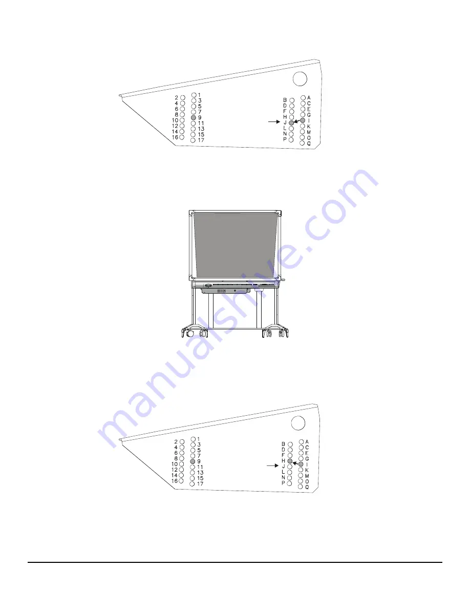
b. Lower the projector plate by one letter location (for example, lower the plate from I-9 to J-9) and then replace and 

secure the fastening hardware. 

c. Repeat if the keystone differential between the top and bottom of the image remains greater than  3/4". Proceed to 

step 4.

3. If the image is wider at the top than the bottom (in excess of 3/4"), adjust the projector so that it’s slightly angled 

upwards, as described in the following steps.

a. While a second person supports the projector, use the security key to loosen and then remove the two button-head 

screws

 in the letter locations only. 

b. Raise the projector plate by one letter location (for example, raise the plate from I-9 to H-9) and then replace and 

secure the fastening hardware. 

c. Repeat if the keystone differential between the top and bottom of the image remains greater than  3/4".

4. Move to the front of the cabinet, and use the supplied 7/16" nut driver to turn the bolt inside the Electronics Tray access 

hole counterclockwise, adjusting the angle of the small mirror to raise the top of the image to the meet the upper frame 
of the cabinet. 

Move the 

projector plate 
downwards at 
the letter screw 
location only

Move the 

projector plate 
upwards at the 
letter screw 
location only.

Summary of Contents for VT560

Page 1: ...om the wall Press the caster tab locks down to lock the wheels again and then extend the anti tip feet 2 Using the height adjustment handle raise the unit to allow easier access to the projector 3 Shut down the computer and then press and hold the Lamp Off button in the Control Panel until the screen turns black approximately three seconds Release the button and the projector lamp powers off in 60...

Page 2: ...tor plate assembly to the two sides of the projector platform Carefully collect and place the four screws and eight washers nearby as you ll need them when you install the replacement projector IMPORTANT Take note of the cable connectors as you disconnect them as you ll connect them to the same ports in the replacement projector CAUTION When using wire cutters to cut a tie wrap be very careful not...

Page 3: ...ity key to loosen and then remove the three sets of button head screws split washers lock washers and spacers that secure the projector to the projector plate Carefully collect them all and place them nearby as you ll need them when you install the replacement projector Remove the projector and set it aside Button Head Screws Split Washers and Lock Washers x 2 Projector Plate Projector Platform ...

Page 4: ... and then insert the three sets of TORX security button head screws split washers and flat washers removed in the previous procedure through the slots in the plate and into the three spacers We recommend that you position the plate so that the slots are centered over the spacers To install the replacement projector IMPORTANT Assemble the security screws split washers and flat washers in the order ...

Page 5: ...ctor and its attached plate in place use the security key to secure the assembly to the appropriate number and letter locations on the left and right sides of the platform using the four sets of button head screws split washers and flat washers you removed previously Make sure the screws are tightly secured NOTE Depending on the height of the projected image further adjustments may be necessary la...

Page 6: ...p On button in the Control Panel Aligning the Projected Image You will need to adjust the projector to obtain a focused image that fits the screen The most obvious misalignment will be on the vertical axis You will notice that the image is about three inches lower than the screen frame Perform the procedures that follow to slide the image up to the top of the screen as well as make other minor ima...

Page 7: ... need to remove the view port cover attached with hook and loop fastener strips to view the image from the rear Grasp the view port cover in the middle of each short edge and pull it away from the cabinet 1 Move to the front of the unit and crouch down facing the screen 2 Look underneath the pen tray and locate the Electronics Tray Locate a large access hole covered with a plastic cap on the right...

Page 8: ... the best starting point for further small mirror adjustments 5 Move to the rear of the cabinet and use the security key to loosen the three button head screws that secure the projector to the projector plate 6 Slide the projector as far forward towards the screen as possible and then tighten the screws you just loosened The top of the screen image should be approximately 3 3 5 from the upper fram...

Page 9: ...r example raise the plate from I 9 to H 8 c Replace and secure the fastening hardware with the security key 7 Move to the front of the cabinet and use the supplied 7 16 nut driver to turn the bolt inside the Electronics Tray access hole counterclockwise adjusting the angle of the small mirror This raises the image to meet the upper frame of the cabinet IMPORTANT Before you begin note that each ver...

Page 10: ...cult to actually see these threads so you may need to reach inside the access hole and feel the threads with your fingers 8 Enlarge the image to fill the screen as follows a Using the security key loosen the three screws and washers that secure the projector to the projector plate b Move the projector backwards away from the screen until the image enlarges enough to fill the screen c Tighten the s...

Page 11: ...orm the two procedures below CAUTION Do not use the blue focus ring that surrounds the projector to adjust focus If you move this ring you may cause the lenses to separate Although the NEC VT560 User s Manual tells you to use the blue focus ring to obtain the best image you must disregard this information Rather use the zoom lever on the projector to adjust focus This lever has been altered so tha...

Page 12: ...hind the projector and look at the projected image through the view port 2 While carefully observing the bottom edge of the image at the right side use the supplied 7 16 nut driver to loosen or tighten the nut that s located on the right side of the projector plate as required 1 Crouch behind the projector and look at the projected image through the view port To adjust image roll To adjust the ima...

Page 13: ...ds with your fingers This adjusts the angle of the small mirror so that it s optimally aligned with the large rear mirror This is the best starting point for further adjustment 2 If the image is narrower at the top than the bottom in excess of 3 4 adjust the projector so that it s slightly angled downwards as described in the following steps a While a second person supports the projector use the s...

Page 14: ...ojector use the security key to loosen and then remove the two button head screws in the letter locations only b Raise the projector plate by one letter location for example raise the plate from I 9 to H 9 and then replace and secure the fastening hardware c Repeat if the keystone differential between the top and bottom of the image remains greater than 3 4 4 Move to the front of the cabinet and u...

Page 15: ...ing Projector Settings The optimal NEC VT560 projector settings for operation in the 2000i cabinet are slightly different from the factory default settings Please ensure your projector has the settings indicated below 1 Press the Menu button on the projector remote control or on the projector you ll have to reach under the projector 2 Select Setup Orientation Ceiling Rear to orient the projected i...

Reviews: