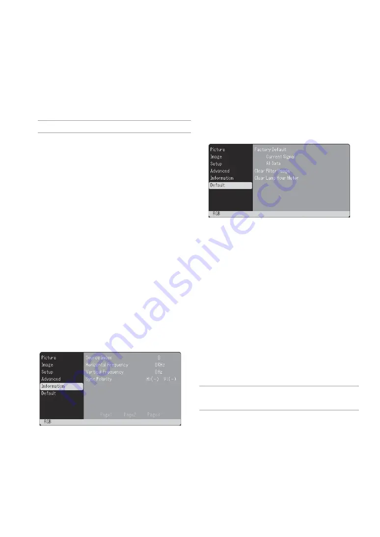
background image

E-24

Default

Returning to Factory Default [Factory Default]
The Factory Default feature allows you to change adjustments and set-
ting to the factory preset for source except the following:

<Current Signal>
Resets the adjustments for the current signal to the factory preset lev-
els.
The items that can be reset are: Brightness, Contrast, Color, Hue, Sharp-
ness, Aspect Ratio, Horizontal Position, Vertical Position, Clock, Phase
and Picture Management.

<All Data>
Reset all the adjustments and settings for all the signals to the factory
preset.
The items can be reset except Language, Lamp Remaining Time, Lamp
Hour Meter and Filter Usage. To reset the lamp usage time, see “Clear
Lamp Hour Meter” and “Clear Filter Usage”.

Resetting the Filter Usage Hours [Clear Filter Usage]
Resets the filter usage back to zero. Selecting this option displays
submenu for a confirmation.

Clearing Lamp Hour Meter [Clear Lamp Hour Meter]
Resets the lamp clock back to zero. Selecting this option displays
submenu for a confirmation.

NOTE: The projector will turn off and go into standby mode after 3100 hours of
service. If this happens, press and hold the ON/STAND BY and CANCEL buttons
on the remote control simultaneously for a minimum of 10 seconds to reset the
lamp clock back to zero. Do this only after replacing the lamp.

[Page 1]
Source Index
Horizontal Frequency
Vertical Frequency
Sync Polarity

[Page 2]
Signal Type
Video Type
Sync Type
Interlace

[Page 3]
Remaining Lamp Time (%)*
Lamp Hour Meter (H)
Filter Usage
Projector Usage
* The progress indicator shows the percent-

age of remaining bulb life. The value in-
forms you of the amount of lamp usage.
When the remaining lamp time reaches 0,
the Remaining Lamp Time bar indicator
changes from 0% to 100 Hours and starts
counting down.
If the remaining lamp time reaches 0 hours,
the projector will not turn on.

Enabling Auto Adjust [Auto Adjust]

When “Auto Adjust” is set to “On”, the projector automatically deter-
mines the best resolution for the current RGB input signal to project
an image using NEC’s Advanced AccuBlend Intelligent Pixel Blend-
ing Technology.
The image can be automatically adjusted for position and stability;
“Horizontal Position”, “Vertical Position”, “Clock” and “Phase”.
On .................. Automatically adjusts image “Horizontal Position”,

“Vertical Position”, “Clock” and “Phase”.

Off .................. User can adjust the image display functions (“Hori-

zontal Position”, “Vertical Position”, “Clock” and
“Phase”) manually.

NOTE: Selecting “Ceiling front” or “Ceiling rear” for “Orientation” will auto-
matically turn on this feature.

Adjusting Position/Clock (when Auto Adjust is off)

This allows you to manually adjust the image horizontally and verti-
cally, and adjust Clock and Phase.

<Horizontal/Vertical>
Adjusts the image location horizontally and vertically.
This adjustment is made automatically when the Auto Adjust is turned
on.

<Clock>
Use this item with the “Auto Adjust off” to fine tune the computer
image or to remove any vertical banding that might appear. This func-
tion adjusts the clock frequencies that eliminate the horizontal band-
ing in the image. This adjustment may be necessary when you con-
nect your computer for the first time. This adjustment is made auto-
matically when the Auto Adjust is turned on.

<Phase>
Use this item to adjust the clock phase or to reduce video noise, dot
interference or cross talk. (This is evident when part of your image
appears to be shimmering.)
Use “Phase” only after the “Clock” is complete.
This adjustment is made automatically when the Auto Adjust is turned
on.

Selecting Communication Speed [Communication Speed]
This feature sets the baud rate of the PC Control port (DIN 8 Pin). It
supports data rates from 4800 to 19200 bps.
The default is 19200 bps.
Select the appropriate baud rate for your equipment to be connected
(depending on the equipment, a lower baud rate may be recommended
for long cable runs).

Information

Displays the status of the current signal and lamp usage. This item has
three pages. The information included is as follows:

Summary of Contents for VT46

Page 1: ...Portable Projector VT46 User s Manual ...

Page 2: ...h the instructions may cause harmful interference to radio communications However there is no guar antee that interference will not occur in a particular installa tion If this equipment does cause harmful interference to radio or television reception which can be determined by turning the equipment off and on the user is encouraged to try to correct the interference by one or more of the following...

Page 3: ...N 1 Do not try to touch the ventilation outlet on the left side when seen from the front as it can become heated while the projector is turned on 2 Do no use the tilt foot for purposes other than originally intended Misuses such as gripping the tilt foot or hanging on the wall can cause damage to the projector 3 Enable High Speed Fan mode if you continue to use the projector for consecutive days F...

Page 4: ...rtion Keystone E 21 Saving Vertical Keystone Correction Keystone Save E 21 Selecting Aspect Ratio Aspect Ratio E 22 Adjusting the Vertical Position of Image Cinema Position for Cinema only E 22 Setup E 22 Selecting Menu Language Language E 22 Selecting Menu Color Menu Color Select E 22 Selecting Menu Display Time Menu Display Time E 22 Selecting a Color or Logo for Background Background E 22 Selec...

Page 5: ...with Advanced AccuBlend 2 Macintosh component signal YCbCr YPbPr or any other RGB signals within a horizontal frequency range of 24 to 100 kHz and a vertical frequency range of 50 to 120 Hz This includes NTSC PAL PAL N PAL M PAL60 SECAM and NTSC4 43 stan dard video signals 2 A UXGA 1600 1200 SXGA 1280 1024 and XGA 1024 768 image are displayed with NEC s Advanced AccuBlend NOTE Composite video stan...

Page 6: ...ilation inlet Filter Cover Lens Cap Lens Adjustable Tilt Foot See page E 16 AC Input Connect the supplied power cable s two pin plug here and plug the other end into an active wall outlet See page E 14 Main Power Switch When you plug the supplied power cable into an active wall outlet and turn on the Main Power switch the POWER indicator turns orange and the projector is in standby mode See page E...

Page 7: ...oon as possible See page E 25 See the Lamp Indicator section on page E 27 for more details 5 VIDEO Button Press this button to select a video source from a VCR DVD player laser disc player or document camera 6 S VIDEO Button Press this button to select an S Video source from a VCR DVD player laser disc player or document camera 7 RGB Button Press this button to select an RGB source from computer o...

Page 8: ...nication protocol to con trol the projector If you are writing your own program typical PC control codes are on page E 32 Terminal Panel Features 1 2 5 3 4 Part Names of the Remote Control 1 Infrared Transmitter Direct the remote control toward the remote sensor on the projector cabinet 2 MENU Button Displays the menu for various settings and adjustments 3 SELECT GHFE Volume Buttons GH Use these b...

Page 9: ...tery is incorrectly replaced Replace only with the same or equivalent type recommended by the manufacturer Dispose of used batteries according to your local regulations Operating Range for Wireless Remote Control Remote control The infrared signal operates by line of sight up to a distance of about 22 feet 7 m and within a 60 degree angle of the remote sensor on the projector cabinet The projector...

Page 10: ...uter or video equip ment to the projector See page E 12 14 3Connect the supplied power cable See page E 14 NOTE Ensure that the power cable and any other cables are disconnected before moving the projector When moving the projector or when it is not in use cover the lens with the lens cap 300 240 406 4 W X304 8 H 160 W X120 H 365 8 W X274 3 H 144 W X108 H 304 8 W X228 6 H 120 W X90 H 243 8 W X182 ...

Page 11: ...400 4590 5510 5510 6610 6130 7350 6440 7720 7360 8830 8290 9940 9210 11050 mm 130 150 180 250 370 440 490 520 550 610 740 920 1110 1230 1290 1470 1660 1840 mm 533 635 762 1016 1524 1829 2032 2134 2286 2540 3048 3810 4572 5080 5334 6096 6858 7620 mm 427 508 610 813 1219 1463 1626 1707 1829 2032 2438 3048 3658 4064 4267 4877 5486 6096 inch 21 25 30 40 60 72 80 84 90 100 120 150 180 200 210 240 270 3...

Page 12: ...pressive pre sentation To connect to a PC or Macintosh simply 1 Turn off the power to your projector and computer 2 Use the supplied signal cable to connect your PC or Macintosh to the projector 3 Turn on the projector and the computer 4 If the projector goes blank after a period of inactivity it may be caused by a screen saver installed on the computer you ve connected to the projector To connect...

Page 13: ...e op tional 15 pin to RCA female 3 cable to connect your DVD player to the RGB IN connector on the projector Component video RCA 3 cable not supplied For a DVD player without component video Y Cb Cr output use common RCA cables not provided to connect a composite VIDEO output of the DVD player to the Video Input of the projector 3 Turn on the projector and DVD player NOTE Refer to your DVD player ...

Page 14: ...Use an audio cable not supplied to connect the audio from your VCR or laser disc player to your audio equipment if your VCR or laser disc player has this capability Be careful to keep your right and left channel connections correct for stereo sound 3 Turn on the projector and the VCR or laser disc player NOTE Refer to your VCR or laser disc player owner s manual for more informa tion about your eq...

Page 15: ...h Norwegian Finnish Portuguese and Czech To select a menu language follow these steps 1 Use the SELECT G or H button to select one of the 19 languages for the menu After this has been done you can proceed to the menu operation If you want you can select the menu language later See Language on page E 22 NOTE Immediately after turning on the projector screen flicker may occur This is not a fault Wai...

Page 16: ...end the adjustable tilt feet maximum height 3 Push down the Adjustable Tilt Foot Levers 4 Lower the front of the projector to the desired height max 40mm 1 6 and release the Adjustable Tilt Foot Lever to lock the Adjust able tilt foot There is approximately 10 degrees of up and down ad justment for the front of the projector Adjustable Tilt Foot Lever CAUTION Do not use the tilt foot for purposes ...

Page 17: ...to adjust Clock and Phase manually See page E 24 Turning Up or Down Volume Sound level from the speaker on the projector can be adjusted NOTE When the menu appears you cannot adjust the volume increase volume Turning off the Projector To turn off the projector First press the POWER ON STAND BY button on the projector cabi net or the remote control The Power Off Are you sure message will appear Sec...

Page 18: ...e menu for the item you want to adjust or set 3 Press the SELECT E button or the ENTER button on the remote control or the projector cabinet to select a submenu or item 4 Adjust the level or turn the selected item on or off by using SELECT F or E buttons on the remote control or the projector cabinet The on screen slide bar will show you the amount of increase or decrease 5 Changes are stored unti...

Page 19: ...djust On Off Vertical Horizontal Clock Phase Communication Speed 4800 9600 19200 Setup Language Language 1 English Deutsch Français Italiano Español Português Nederlands Language 2 Svenska Norsk Suomi Česky Magyar Polski Türkçe Language 3 Menu Color Select Color Monochrome Menu Display Time Manual Auto 5 sec Auto 15sec Auto 45 sec Background Blue Black Logo Orientation Desktop Front Ceiling Rear D...

Page 20: ...iangle indicates the item is active Tab Indicates a group of features in a dialog box Select ing on any tab brings its page to the front Radio button Use this round button to select an option in a dialog box Check mark Indicates the item is selected Slide bar Indicates settings or the direction of adjustment Key symbol Indicates the Control Panel Key Lock is enabled Menu Elements Title Slide bar H...

Page 21: ...blue The red level is used as reference This adjustment is only valid for Video and Component inputs not valid for RGB Picture Management This option allows you to adjust neutral tint for yellow cyan or ma genta There are 5 factory presets optimized for various types of images or you can set user adjustable settings Presentation Recommended for making a presentation using a PowerPoint file Video R...

Page 22: ... thorized user using the Menu When a keyword is set turning on the projector will display the Keyword input screen Unless the correct key word is entered the projector cannot project an image To enable the Security function 1 Select Advanced Security and press the F button to select On Normal Wide Zoom Cinema Native Standard 4 3 Aspect Left and right stretched Left and right stretched When 16 9 is...

Page 23: ...mputer or Component for a component video source such as a DVD player Normally select RGB Component and the projector automatically detects a component signal However there may be some compo nent signals that the projector is unable to detect If this is the case select Component Select Scart for the European Scart Video S Video System Select This feature enables you to select composite video stand...

Page 24: ...is set to On the projector automatically deter mines the best resolution for the current RGB input signal to project an image using NEC s Advanced AccuBlend Intelligent Pixel Blend ing Technology The image can be automatically adjusted for position and stability Horizontal Position Vertical Position Clock and Phase On Automatically adjusts image Horizontal Position Vertical Position Clock and Phas...

Page 25: ...ntact your NEC dealer for lamp replace ment To replace the lamp 1 Loosen the lamp cover screw until the screwdriver goes into a free wheeling condition and remove the lamp cover The lamp cover screw is not removable 3 Insert a new lamp housing until the lamp housing is plugged into the socket CAUTION Do not use a lamp other than the NEC replacement lamp VT60LP Order this from your NEC dealer Secur...

Page 26: ...o page E 24 for resetting the filter usage time To replace the filter sponge 1 Remove the filter cover by pushing up on the catch of the cover until you feel it detach 2 Gently peel off the filter sponge and replace it with the new one 3 Reinstall the new filter cover NOTE Do not wash the filter with soap and water Soap and water will damage the filter membrane Before replacing the filter remove d...

Page 27: ... cycle 0 5 sec On 0 5 sec Off 6 cycle 0 5 sec On 0 5 sec Off Normal Lamp cover error or lamp housing error Temperature error Fan error Lamp error Re firing the lamp Control Panel key locked Replace the lamp cover or lamp housing correctly The projector is overheated Move the projector to a cooler location Fans will not work correctly Lamp fails to light Wait a full minute and then turn on again Th...

Page 28: ...stments to factory preset levels using Factory Default in the menu See page E 24 Reposition the projector to improve its angle to the screen See page E 16 Use the Keystone correction function to correct the trapezoid distortion See page E 21 Adjust the focus See page E 16 Reposition the projector to improve its angle to the screen See page E 16 Ensure that the distance between the projector and sc...

Page 29: ...es SECAM 350 TV lines YCbCr 800 TV lines RGB 800 dots H 600 dots V External Control RS232 IR Sync Compatibility Separate Sync Composite Sync Sync on G Built in Speaker 1W monaural Power Requirement 100 120V AC 200 240V AC 50 60 Hz Input Current 2 3A 100 120V AC 1 1A 200 240V AC Power Consumption 220W 7 5W in Standby mode Mechanical Installation Orientation Desktop Front Desktop Rear Ceiling Front ...

Page 30: ...round 6 Red Ground Cr Ground 7 Green Ground Y Ground 8 Blue Ground Cb Ground 9 No Connection 10 Sync Signal Ground 11 SCART Sync Sync 12 Bi directional DATA SDA 13 Horizontal Sync or Composite Sync 14 Vertical Sync 15 Data Clock Signal Level Video signal 0 7Vp p Analog Sync signal TTL level 5 1 4 2 3 10 11 12 13 14 15 6 9 7 8 99 2 3 9 96 3 8 230 9 1 245 9 6 89 3 5 73 5 2 9 310 12 2 1 6 41 7 Lens c...

Page 31: ...2 900 71 736 76 05 VESA 1280 960 60 60 VESA 1280 1024 63 981 60 02 MAC 1280 1024 69 89 65 18 HP 1280 1024 78 125 72 01 SUN 1280 1024 81 13 76 11 VESA 1280 1024 79 976 75 03 VESA 1280 1024 91 146 85 02 SXGA 1400 1050 HDTV 1080p 1920 1080 67 5 60 Progressive SDTV 576i 625i 15 6 50 SDTV 576p 625p 31 5 50 HDTV 1080i 1125i 1920 1080 33 75 60 Interlace HDTV 1080i 1125i 1920 1080 28 125 50 Interlace HDTV...

Page 32: ...jector PC Control Codes Function Code Data POWER ON 02H 00H 00H 00H 00H 02H POWER OFF 02H 01H 00H 00H 00H 03H INPUT SELECT RGB 02H 03H 00H 00H 02H 01H 01H 09H INPUT SELECT VIDEO 02H 03H 00H 00H 02H 01H 06H 0EH INPUT SELECT S VIDEO 02H 03H 00H 00H 02H 01H 0BH 13H PICTURE MUTE ON 02H 10H 00H 00H 00H 12H PICTURE MUTE OFF 02H 11H 00H 00H 00H 13H SOUND MUTE ON 02H 12H 00H 00H 00H 14H SOUND MUTE OFF 02H...

Page 33: ...model name serial number and name of the store of purchase are not indicated on the warranty or have been altered 2 Problems or damage caused by dropping or shocks during ship ment or movement by the customer or by improper handling by the customers 3 Problems or damage caused by improper usage or unwarrant able alterations or repairs by the customer 4 Problems or damage caused by fire salt damage...

Page 34: ...x Line 65 6 274 2226 Email Address daniel rsc necsin nec com sg WEB Address http www nec com sg Regions Covered Singapore Hyosung Data System Ltd Address 7th Floor Cheongdam Building 52 Cheongdam Dong Kangnam Ku Seoul Korea 135 100 Telephone 82 2 510 0234 Fax Line 82 2 540 3590 Email Address hds ykc hyosung com Regions Covered South Korea Lenso Communication Co Ltd Address 292 Lenso House 4 1st Fl...

Page 35: ... I also confirm following information is correct Regards Application Sheet for TravelCare Service Program Date P 1 Country product purchased User s Company Name User s Company Address Phone No Fax No User s Name User s Address Phone No Fax No Local Contact office Local Contact office Address Phone No Fax No User s Model Name Date of Purchase Serial No on cabinet Problem of units per User Required ...

Page 36: ...n 1 Accidents transportation neglect misuse abuse water dust smoke or default of or by the Customer its employees or agents or any third party 2 Failure or fluctuation of electrical power electrical circuitry air condi tioning humidity control or other environmental conditions such as use it in smoking area 3 Any fault in the attachments or associated products or components whether or not supplied...

Page 37: ......

Reviews: