NEC Versa AX Disassembly Manual Download Page 11

Disassembly and Reassembly - 11

12. CD-ROM Drive

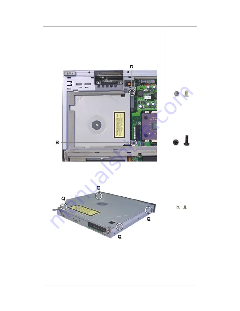
Remove the CD-ROM drive as follows:

a.


Remove the two CD-ROM drive screws (1xD, 1xB).

b.


Slide out the CD-ROM drive.

Fig. 17:  Removing the CD-ROM drive.

c.


Remove the four screws (4xQ) that hold the bracket.

d.


The brackets are now free.

Fig. 18:  The CD-ROM bracket.

13. Top Cover

The procedure below describes how to remove the top cover:

a.


Remove the eight screws of the top cover (4xA, 4 at top) (1xM
below right) (2xB, centre right, near power switch) (1xR, at
bottom left).

b.


Take away the top cover

D

B

Q

Summary of Contents for Versa AX

Page 1: ...Versa AX Disassembly n Required Tools n Disassembly Instructions n Reassembly Instructions ...

Page 2: ...ns are clarified by images of the part that is being removed or disassembled Furthermore the screws that are removed are shown next to the image of the parts themselves When disassembling the system unit follow these general rules n Do not disassemble the system into parts that are smaller than those specified in the instructions n Label all removed connectors Note where the connector goes and in ...

Page 3: ...he battery out of the bottom base Fig 1 Battery and modem cap removal 2 Modem The following steps describe how to remove the modem a Remove the screw of the modem cap 1x A1 b Slide open the modem cap and remove it Fig 2 How to take out the modem c Disconnect the modem connector cable d Release the modem board like an SO DIMM module e Finally take out the modem board A ...

Page 4: ...n the underside b Lift up the front cover c Disconnect the touchpad connector d The front cover is now free from the notebook 5 VersaGlide Touchpad Disassemble the VersaGlide touchpad as follows a Remove the flat cable of the touchpad buttons b Disconnect the touchpad connector cable c Remove the three button board screws 3xC d Remove the button board e Carefully slide the touchpad frame down a li...

Page 5: ...the instructions for removing the hard disk drive a Remove the two screws that hold the hard disk drive and it s connector Note During assembly the 3 rd screw for fixing the HDD is inserted during the assembly of the Front Cover b Lift up the hard disk drive and remove it Fig 5 Hard disk drive C D ...

Page 6: ...or a Remove the connector from the hard disk drive b Remove the four screws 4xE from the HDD bracket Fig 6 Hard disk drive bracket 8 Keyboard Remove the keyboard as follows a Slide the power button cover above the keyboard slightly to the right to unlock it b Take away the power button cover Fig 7 Sliding off the power button cover E ...

Page 7: ...d cable 9 LCD Screen Remove the LCD screen according to the following procedure a Remove the two screws 2xA on the back of the system Fig 9 Removing the LCD screen back b Slide the LCD hinge covers outwards c Remove the two screws 2xA from the LCD cable box d Remove the four screws on the LCD hinges 4xF Fig 10 Removing the LCD screen front A A F ...

Page 8: ...rubber bumpers 2xG at the top to clear two screws underneath d Remove the two screws 2x I e Take off the LCD front bezel Fig 11 Taking off the front bezel f Remove the LCD lock and its spring g Remove the single screw that holds the inverter board 1xD h Lift up the inverterboard and disconnect the two cables attached to it i Remove the screw 1xD and the placeholder 1xK for the cable that runs to t...

Page 9: ...up the LCD panel from the back cover m Remove the LCD cable connector from the back of the panel Fig 13 Removing the LCD cable connector n Remove the six screws holding the LCD hinges in place 6x J o Take away the hinges Fig 14 The hinges on the LCD back panel L D K J ...

Page 10: ...crews of the heatplate cannot be removed as they are locked in their position They can only be loosened b Take away the heatplate Fig 15 Taking away the heatplate Note To securely re seat the heatplate during re assembly you should first start with screw 1 then 2 etc c Disconnect the fan power cable Fig 16 The power fan cable and the DC DC board screw D ...

Page 11: ...7 Removing the CD ROM drive c Remove the four screws 4xQ that hold the bracket d The brackets are now free Fig 18 The CD ROM bracket 13 Top Cover The procedure below describes how to remove the top cover a Remove the eight screws of the top cover 4xA 4 at top 1xM below right 2xB centre right near power switch 1xR at bottom left b Take away the top cover D B Q ...

Page 12: ...ound board a Remove the single screw of the soundboard 1xM b Lift the board and disconnect the speaker cable the bridge battery cable and the microphone cable c Disconnect the soundboard from the mainboard Note During re assembly the cables should first be connected before placing the board Fig 20 Sound board removal A B M S M ...

Page 13: ...take away the I O board d Disconnect the charger board from the I O board 16 Floppy Disk Drive Follow the steps below to in order to remove the floppy disk drive a Remove the floppy disk drive screw 1xS Fig 22 Removing the floppy disk drive b Remove the floppy disk drive including the bracket c Remove the four screws 4xM that hold the FDD bracket d Remove the FDD bracket from the floppy disk drive...

Page 14: ...e Battery Here you find the order in which to take out the microphone speakers and bridge battery a Remove the microphone b Remove the bridge battery c Remove both speakers Note Take care to properly work away the cables during assembly Fig 24 Removing the microphone speakers and bridge battery M ...

Page 15: ... the one used for unlocking the CPU b Remove the CPU from the socket 19 RJ 11 Connector Next is described how to remove the RJ 11 connector a Turn the unit upside down b Remove the modem connector cable from the RJ 11 connector c Turn the base unit right side up d Slide out the modem cable cover e Disconnect the modem connector cable f Remove the screw 1xS from the RJ 11 connector g Remove the con...

Page 16: ...dure below explains how to remove the mainboard from the bottom base assembly a Remove the two screws 1xS 1xP that hold the CD ROM rail b Remove the single normal screw 1xT c Remove the two bus screws next to LCD connector 2xU d Remove the three bus screws from the mainboard 3xP e Remove the five screws from the mainboard 4xS f Remove one screw 1xO Note Beware that slide rails for the CD ROM drive...

Page 17: ...They are located next to the I O ports 6xV Fig 28 Removing the screws holding the mainboard from the rear i Remove the mainboard 22 I O Bracket Remove the I O bracket from the bottom base as follows a Remove two screws 2xI Fig 29 Bottom of the I O bracket b Remove the four stickers that hide the screws c Remove the for screws 4xI S U P O T V I ...

Page 18: ...everse of the disassembly process Use care to ensure that all cables and screws are returned to their proper positions Small Parts Overview Below you will find the overview of the small parts screws bumpers stickers and small brackets used during the disassembly and reassembly of the notebook A B C D E G H I J K L M N O P Q S T U V ...

Reviews: