background image

English-4

Figure C.1

Figure C.2

Highest

Stand

Position

Quick Start

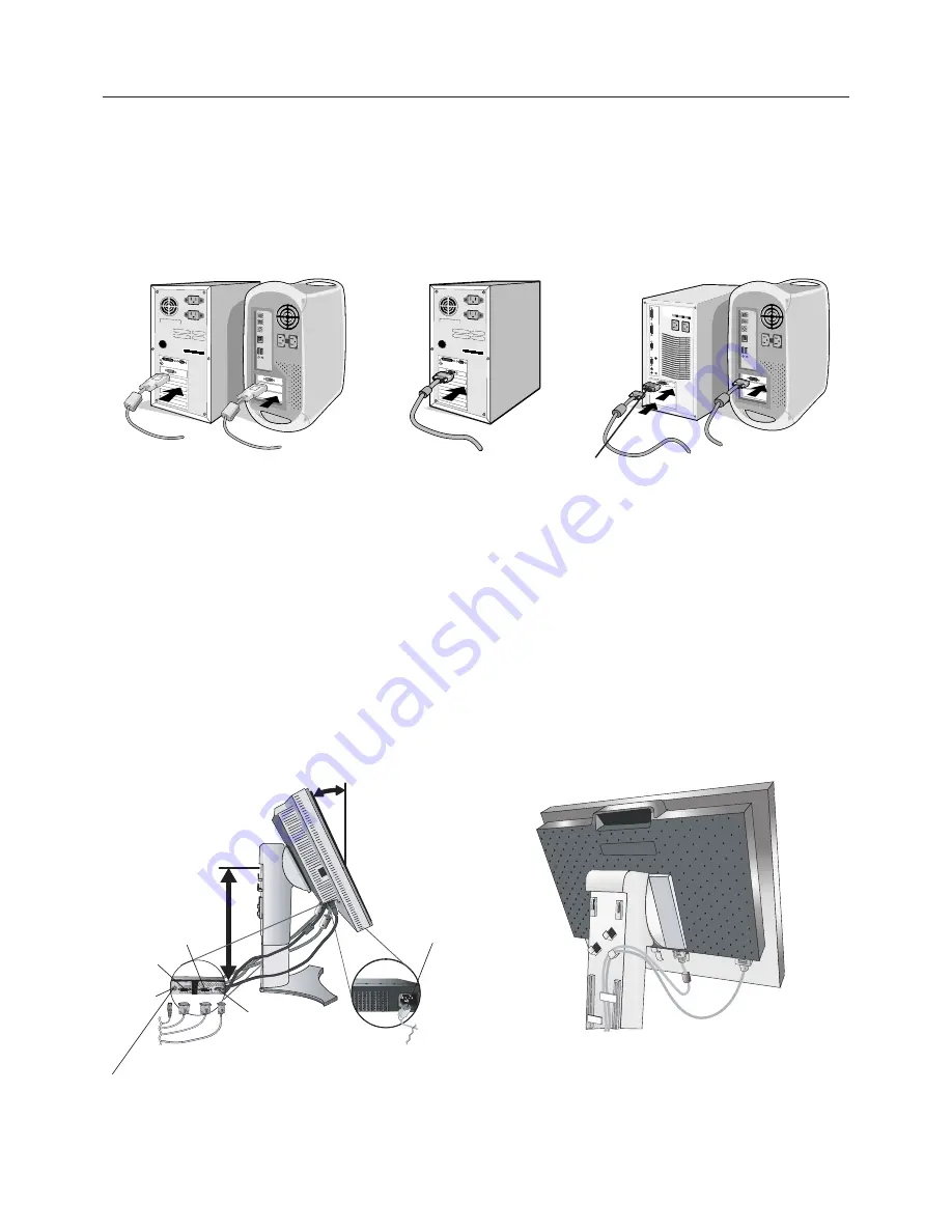
To attach the LCD monitor to your system, follow these instructions:

1. Turn off the power to your computer.

2.

For the PC or MAC with DVI digital output:

 Connect the DVI signal cable to the connector of the display card in your

system (

Figure A.1

). Tighten all screws.

For the PC with Analog output:

 Connect the 15-pin mini D-SUB to DVI-A signal cable to the connector of the display

card in your system (

Figure A.2

).

For the MAC:

 Connect the Macintosh cable adapter to the computer, then attach the 15-pin mini D-SUB signal cable to

the Macintosh cable adapter (

Figure B.1

).

NOTE:

Some Macintosh systems do not require a Macintosh cable adapter.

3. Place hands on each side of the monitor to tilt the LCD panel 30-degree angle and lift up to the highest position (

Figure C.1

).

4. Connect all cables to the appropriate connectors (

Figure C.1

).

NOTE:

Incorrect cable connections may result in irregular operation, damage display quality/components of LCD module
and/or shorten the module’s life.

5. To keep the cables neatly organized, place them into the cable management system that is built into the stand.

Place the D-Sub cable (not included) and the power cable into the specific hooks as indicated (

Figure C.2

).

Place the DVI cable and the 15-pin mini D-Sub to DVI-A cable into the hooks as indicated (

Figure C.3

).

When using the monitor in Portrait mode, place the DVI cable and the 15-pin mini D-Sub to DVI-A cable into the hooks as
indicated (

Figure C.4

).

6. Make sure all cables are resting flat against the stand (

Figure C.3

).

Please check Tilt, Rise and Lower monitor screen and screen rotation when you manage cables.

Figure A.1

Figure B.1

Macintosh
Cable Adapter
(not included)

Figure A.2

Power cord

30˚ Tilt

DC-OUT

DVI-D

DVI-I

D-SUB

NEC optional product attachment.
Do not use this connector unless specified.

Summary of Contents for SpectraView 2690

Page 1: ...MultiSync LCD2690WUXi SpectraView 2690 User s Manual...

Page 2: ...ion of Conformity English 2 Contents English 3 Quick Start English 4 Controls English 8 Recommended use English 13 Specifications English 15 Features English 16 Troubleshooting English 17 Appendix Eng...

Page 3: ...n approved by and complies with the safety standard of your particular country TO PREVENT FIRE OR SHOCK HAZARDS DO NOT EXPOSE THIS UNIT TO RAIN OR MOISTURE ALSO DO NOT USE THIS UNIT S POLARIZED PLUG W...

Page 4: ...n a particular installation If this equipment does cause harmful interference to radio or television reception which can be determined by turning the equipment off and on the user is encouraged to try...

Page 5: ...DVI D to DVI D cable User s Manual CD ROM Cable Cover Screw x 4 to mount the monitor to a flexible arm page 7 Power Cord Continental User s Manual DVI D to DVI D cable Cable Cover CD ROM 15 pin mini...

Page 6: ...C 1 4 Connect all cables to the appropriate connectors Figure C 1 NOTE Incorrect cable connections may result in irregular operation damage display quality components of LCD module and or shorten the...

Page 7: ...monitor must be turned on Turn on the monitor with the front power button Figure E 1 and the computer NOTE The Vacation Switch is a true on off switch If this switch is on the OFF position the monitor...

Page 8: ...raise the screen place hands on each side of the monitor and lift up to the highest position Figure RL 1 To rotate screen place hands on each side of the monitor screen and turn clockwise from Landsca...

Page 9: ...oval and attach the arm to the monitor Figure F 1 Caution Use ONLY the screws 4 pcs that are included when mounting to avoid damage to the monitor and stand To fulfil the safety requirements the monit...

Page 10: ...he monitor on and off Indicates that the power is on Can be changed between blue and green in the Advanced OSM Control menu Enters the OSM Control menu Enters OSM sub menus Changes the input source wh...

Page 11: ...ls LEFT RIGHT Controls Horizontal Image Position within the display area of the LCD DOWN UP Controls Vertical Image Position within the display area of the LCD H SIZE V SIZE Analog input only Adjusts...

Page 12: ...riginal colour presented by the LCD panel that is unadjustable PROGRAMMABLE The colour tone that was set up with the downloaded application software is reflected NOTE To reset a poor image setting tur...

Page 13: ...lost STANDARD Monitor enters power save mode automatically when the input signal is lost OPTION Monitor enters power save mode automatically when the amount of surrounding light goes below the level t...

Page 14: ...be accessed with the EXIT button FACTORY PRESET Selecting Factory Preset allows you to reset all OSM control settings BRIGHTNESS CONTRAST ECOMODE AUTO BRIGHTNESS BLACK LEVEL IMAGE CONTROL COLOR CONTR...

Page 15: ...e with care Immediately unplug your monitor from the wall outlet and refer servicing to qualified service personnel under the following conditions When the power supply cord or plug is damaged If liqu...

Page 16: ...patterns on the monitor for long periods of time to avoid image persistence after image effects Get regular eye checkups Ergonomics To realize the maximum ergonomics benefits we recommend the followi...

Page 17: ...50 1 at 60 Hz to 75 Hz Digital 1600 x 1200 1 at 60 Hz to 75 Hz Analog 1600 x 1200 1 at 60 Hz Digital 1200 x 1920 1 at 60 Hz 1680 x 1050 1 at 60 Hz to 75 Hz Analog NEC DISPLAY SOLUTIONS cites 1680 x 10...

Page 18: ...ccuracy of your monitor to a variety of standards OSM On Screen Manager Controls Allow you to quickly and easily adjust all elements of your screen image via simple to use on screen menus ErgoDesign F...

Page 19: ...for one hour and a residual image remains the monitor should be turned off for one hour to erase the image NOTE As with all personal display devices NEC DISPLAY SOLUTIONS recommends using a moving sc...

Page 20: ...s by 25 2 Decreases the brightness by 50 CUSTOM Decreases the brightness level as determined by the user ECO Mode Custom Allows the user to set a preferred brightness level when ECO Mode is in use Aut...

Page 21: ...Analog input only FULL and DETAIL Press Left or Right to select Refer to the below table A NTAA SW The Advanced No Touch Auto Adjust function is able to recognize new signals even when Analog input o...

Page 22: ...becomes possible to adjust the H ZOOM V ZOOM and ZOOM POS H ZOOM The image is expanded from 1 to 3 times in the horizontal H EXPANSION direction by Available in Custom 0 01 increments Expansion mode...

Page 23: ...select ON Note Interlaced signals 480i 576i 1080i are not supported If you have any problems please refer to the Troubleshooting section of this User s Manual Video Detect Selects the method of video...

Page 24: ...een will appear indicating the OSM controls are locked out There are three types of OSM LOCK OUT OSM LOCK OUT with BRIGHTNESS and CONTRAST control To activate the OSM Lock Out function press SELECT th...

Page 25: ...reduce the risk of image retention Timing for MOTION can be set so the screen image moves in intervals from every 10 to 900 seconds Timing is set in 10 second increments OPTION Default REDUCED There...

Page 26: ...he schedule indicates that the selected schedule is in effect To select which schedule to set use the up down arrows to move the cursor vertically under the number 1 to 7 of the schedule Use the Down...

Page 27: ...ose the desired brightness level Figure 2 2 Set the DARK level This is the level of brightness that the monitor will go down to when the ambient light level is low Make sure the room is at its darkest...

Page 28: ...Energy saving mode after a certain time beneficial both for the user and the environment Electrical safety Emissions Electromagnetic fields Noise emissions Ecology The product must be prepared for rec...

Page 29: ...ttp www nec display com in Japan or http www necdisplay com in USA Energy Saving This monitor features an advanced energy saving capability When a VESA Display Power Management Signalling DPMS Standar...

Reviews: