background image

12

13

14

79644641

POWER

ON

RGB 2

RGB 1

VIDEO 2

VIDEO 1

POSITION / CONTROL

PROCEED

EXIT

SCAN

NORMAL

SIDE PIN

HEIGHT

WIDTH

BRIGHT CONTRAST MUTE

NORMAL

VOLUME

OFF

DEGAUSS

MULTIMEDIA MONITOR
RD-346E

0

A
D

F

E

7

8

B

C

9

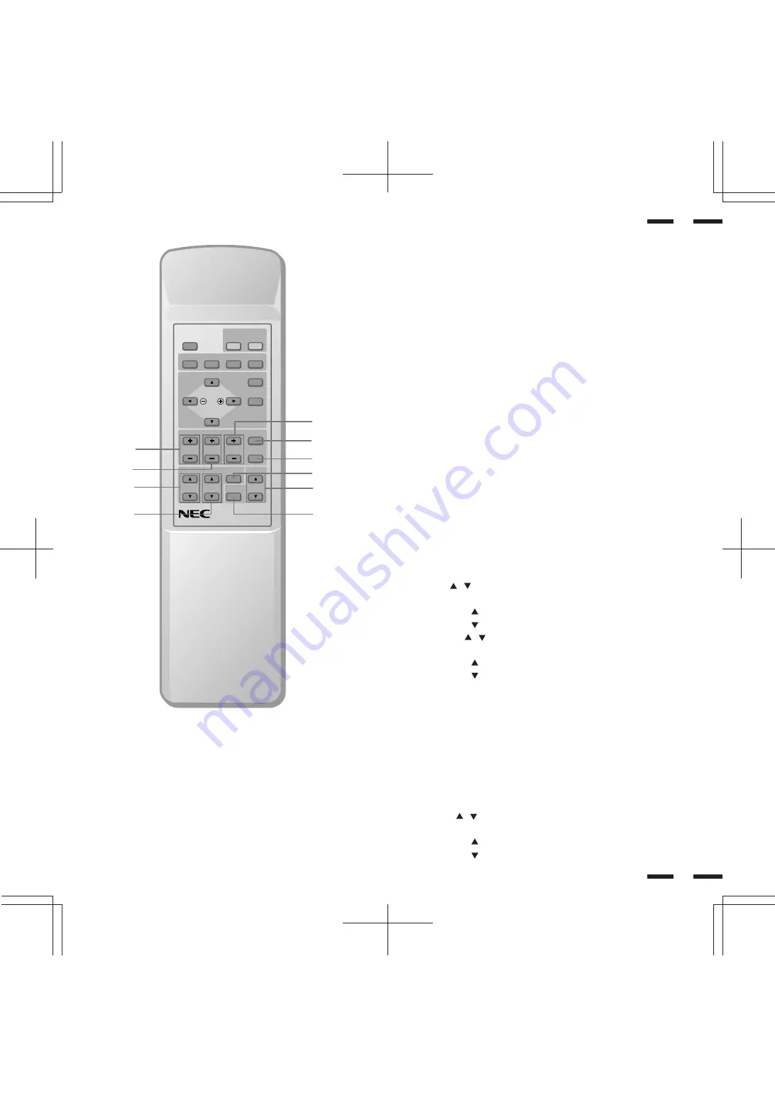
Visual Control

B

BRIGHT (  /   )

Adjusts the overall image and screen brightness.

Press and hold   for a brighter picture.

Press and hold   for a darker picture.

C

CONTRAST (  /  )

Adjusts the image brightness in relation to the background.

Press and hold   for higher contrast.

Press and hold   for lower contrast.

NOTE: The VISUAL CONTROL storing operation is effective only for the

input currently used (VIDEO1, VIDEO 2, RGB 1 or RGB 2).

D

NORMAL

This key resets the visual control settings and recalls the factory preset data.

NOTE: The brightness and contrast adjustment level are factory preset at

the optimum position.

E

MUTE

Press to cancel sound ; press again to restore sound.

NOTE: The other ways to restore sound are to press POWER OFF, then

ON or to press VOLUME keys on the remote control unit.

F

VOLUME (   /   )

Adjusts the volume.

Press and hold   to increase sound.

Press and hold   to decrease sound.

Raster Control

7

WIDTH ( + / -)

Adjusts the horizontal size of the image.

8

HEIGHT ( + / -)

Adjusts the vertical size of the image.

9

SIDE PIN ( + / -)

Adjusts the curvature of the edges of the left and right side of the display

image either inward or outward. The image should be adjusted to attain a

straight line on the left and right sides.

0

SCAN SELECT

Each time this key is pressed, the picture size switches from OVER SCAN

for large size to UNDER SCAN for small size and vice versa. Normally select

OVER SCAN for video display and UNDER SCAN for RGB display.

A

NORMAL

This key resets the raster adjustment settings of user changeable memory

and recalls the factory preset data.

Summary of Contents for R 37 Xtra

Page 1: ...ies Inc 1250 N Arlington Heights Road Suite 500 Itasca Illinois 60143 1248 R 37 Xtra 37 Xtra Printed in Japan 79TH1624 MultiSync is a registered trademark of NEC Technologies Inc in the U S A NEC is r...

Page 2: ...the warranty will be void Moreover there is a serious risk of electric shock 7 Do not attempt to service or repair the unit NEC is not liable for any bodily harm or damage caused if unqualified person...

Page 3: ...ou une tag re la temp rature doit tre maintenue en dessous de 40 C 2 Ne pas utiliser la fiche polaris e du cordon d alimentation avec des prolongateurs ou des prises de courant sauf si les lames peuv...

Page 4: ...s of initial technical adjustments set up including adjustment of user controls These costs are the responsibility of the NECTECH dealer from whom the product was purchased 3 Payment of shipping charg...

Page 5: ...trols Degaussing 27 Using OSM Controls 28 Direct Control Screen 29 Accessing OSM 32 CONTENTS OSM Menus 32 Visual Controls Group 32 H position H width Pin cushion Controls Group 33 V position V height...

Page 6: ...tiSync XP37 Xtra XM37 Xtra monitor provides a list of materials that comes with your monitor and describes the features and controls The features you ll enjoy include Simple controls Let you make all...

Page 7: ...Sensor Window Receives infrared signal from the handheld remote control 4 RGB 2 DTV Press to select an RGB video source that is connected to the RGB 2 input terminals BNC type When you are in the OSM...

Page 8: ...one external control No 6 pin EXT CONTROL of DIP SW must be set to the ON position on all of the monitors B REMOTE IN OUT Connect the optional remote cable included with the optional remote control to...

Page 9: ...computer or another RGB source AUDIO L MONO IN This is where you connect RGB left audio output from a computer or another RGB source AUDIO R THROUGH OUT Connect to a second monitor s RGB right audio...

Page 10: ...ing VIDEO 1 IN and THROUGH OUT BNC type terminals set to HIGH on all but the last monitor Set to 75 on the last monitor only AUDIO R IN This is your right channel audio input for stereo sound AUDIO L...

Page 11: ...a computer connected to the RGB 1 IN terminal RGB 2 Press to select an RGB component video source from a computer NEC scan converter or YPBPR YCBCR Signal source connected to the RGB 2 IN terminal 796...

Page 12: ...factory preset at the optimum position E MUTE Press to cancel sound press again to restore sound NOTE The other ways to restore sound are to press POWER OFF then ON or to press VOLUME keys on the remo...

Page 13: ...e remote control unit for a long period remove the batteries Do not use new and old batteries together or use different types of batteries together Do not take apart the batteries heat them or throw t...

Page 14: ...ifferent IPM modes The following is the description of the LED indicator for the IPM power saving modes Pin No 6 EXT CONTROL When this switch is set to ON the External Control function is activated Se...

Page 15: ...intosh G3 series Installation Wiring Diagram To Mini D SUB 15 Pin input To R G B H CS V inputs BNC To EXTERNAL CONTROL Mini D SUB 15 Pin input NEC IPS 4000 Image Processo XP37 Xtra XM37 Xtra Macintosh...

Page 16: ...the monitor and the VCR or laser disc player NOTE Refer to your VCR or laser disc player owner s manual for more information about your equipment s video output requirements NOTE S VIDEO IN terminals...

Page 17: ...component to relay the signal input at VIDEO 2 IN BNC type or S VIDEO 2 IN 2 Connect the external component mono audio or stereo left channel audio input to L AUDIO 3 Connect the external component s...

Page 18: ...CE 8 OHM RIGHT LEFT INT EXT IN THROUGH OUT 12345678 ON L MONO L MONO L MONO L SPEAKER SELECT INT EXT RIGHT 4 ft 120cm 4 ft 120cm Left Right To connect the monitor to stereo system speakers 1 Connect L...

Page 19: ...which may require demagnetizing to clear the problem Also if powered on for extended periods of time magnetic fields can be produced by the CRT itself causing color impurities In these cases use the D...

Page 20: ...reen press any one of the other keys To end the OSM display press EXIT If no key operation is made within 3 seconds the OSM display will disappear a POSITION CONTROL Press to move the image right Pres...

Page 21: ...rols such as brightness contrast color tint and sharpness BRIGHTNESS Pressing or increases or decreases the image brightness level CONTRAST Pressing or increases or decreases the image contrast level...

Page 22: ...e of the sides to right or to left PIN CORNER Pressing or decreases or increases the curvature of the four corners inward or outward NOTE The V LINEARITY controls allow you to adjust the spacing of th...

Page 23: ...nal H POL indicates the polarity of the horizontal sync signal V POL indicates the polarity of the vertical sync signal NEG indicates the polarity is negative POS indicates the polarity is positive RG...

Page 24: ...T E R N O R M A L A L L V I S U A L N O R M A L A L L N O R M A L P R E S S P R O C E E D T O R E S E T 38 If the monitor does not reproduce the color for a component signal correctly the monitor wil...

Page 25: ...his control is available only when No 8 pin of the DIP switch is set at the ON position The DIP switch is located on the back cabinet OSM keys on the remote control unit function as follows POSITION C...

Page 26: ...nnection Receive Data No Connection Transimit Data No Connection Clear to Send No Connection Request to Send Ground Input Select Input Select Power ON OFF No Connection Degauss ON OFF Signal Ground EX...

Page 27: ...r gives the command to the XP37 Xtra XM37 Xtra the XP37 Xtra XM37 Xtra returns an ACK So make sure that the external equipment receives this ACK The XP37 Xtra XM37 Xtra returns an ACK if it has receiv...

Page 28: ...control directly at Sensor Window Use the remote control unit within 30 left and right of center at a distance of within 22ft Set Pin no 7 of DIP SW to ON SHORT Set Pin no 6 of DIP SW to OFF OPEN Chec...

Page 29: ...Y 1 0Vp p 75 Ohms unbalanced Sync negative S VIDEO Video 1 2 C 0 28Vp p 75 Ohms unbalanced Color burst level Video Output Terminals THROUGH OUT Video 1 2 1 0Vp p 75 Ohms unbalanced BNC Jack Composite...

Page 30: ...B VIDEO 6 MHz at 3dB Display Area RGB 95 Scan Typically VIDEO 7 Overscan Blanking Horizontal 15 75kHz 7 0 sec 30kHz fH 50kHz 3 3 sec 51kHz fH 80kHz 2 9 sec 81kHz fH 100kHz 2 7 sec Vertical 0 4 msec Cu...

Page 31: ...NTROL DIP SW AC IN SPEAKER SELECT EXT SPEAKER RGB 2 AUDIO AUDIO HIGH 75 R MONO IN THROUGH OUT IN THROUGH OUT THROUGH OUT IN BNC S HIGH 75 THROUGH OUT IN R THROUGH OUT IN R THROUGH OUT IN BNC S HIGH 75...

Page 32: ...ence Chart Separate Sync Timing Charts Composite Sync 54 A B C D E VIDEO O P Q R S VIDEO Sync Polarity Positive Negative HORIZONTAL VERTICAL VIDEO A B C D E O P Q R S VIDEO Sync Polarity Positive Nega...

Page 33: ...d 2 0 sec at sync on green and 1 2 sec at others except when at 15KHz Horizontal blanking should exceed 7 0 se at fH 15 75kHz 3 3 sec at 30 kHz fH 50kHz 2 9 usec at 51kHz fH 80kHz and 2 7 sec at 81kHz...

Page 34: ...4 sec 2 000 sec 3 556 sec 22 222 sec 0 667 sec 1024 768 48 363KHz 20 677 sec 2 092 sec 2 462 sec 15 754 sec 0 369 sec VESA 1024 768 at 60Hz 1024 768 35 587KHz 28 100 sec 3 910 sec 1 247 sec 22 760 sec...

Page 35: ...SA 640 480 at 72Hz VESA 800 600 at 56Hz 800 600 56 250Hz 17 778msec 0 057msec 0 626msec 17 067msec 0 028msec 1024 768 60 000Hz 16 667msec 0 124msec 0 600msec 15 880msec 0 062msec VESA 1024 768 at 60Hz...

Page 36: ...2 VIDEO NTSC VIDEO PAL SECAM VESAI Standard 640x480 31 5KHz 60Hz IBM 640x350 31 5KHz 71Hz IBM 640x400 31 5KHz 71Hz MAC 13 35 00KHz 66 67Hz VESA 800x600 35 156KHz 56 250Hz VESA 1024x768 35 522KHz 43 47...

Page 37: ...ased If this is a reseller who is unable to provide service call NEC directly at 1 800 836 0655 DOA Policy A product is considered DOA if it fails to function according to current published specificat...

Page 38: ...e received including interference that may cause undesired operation U S Responsible Party Address Tel No NEC Technologies Inc 1250 North Arlington Heights Road Itasca Illinois 60143 1248 630 467 5000...

Reviews: