background image

7

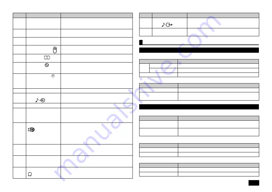
Power LED

Drive activity LED

Caps lock indicator LED

Scroll Lock indicator LED

Num Lock indicator LED

(9)

Air vent

These holes are designed to allow internal heat to 
escape.
Please be careful not to leave the air vent blocked.

(10)

Chassis lock

A security cable (sold separately) can be attached 
to this slot.

(11)

AC power input jack

A jack used to supply power to the machine.
Connects to the supplied power cord.

(12)

PS/2 mouse port (

)

A port used to connect a PS/2 (MiniDIN 6-Pin) 
mouse.

(13)

Serial port (

)

This is used to connect to devices that have a 
serial port.

(14)

Power LED (

)

It indicates the power status. This indicator 
continues to light when the power is on, and it 
flashes in the Sleep mode.

(15)

Drive activity LED ( )

This indicator lights up when accessing the hard 
disk or the optical drive.
Do not press the power switch when the Drive activity 
LED is lit. It may cause damage to the hard disk.

(16)

Stand

This keeps the computer stable.

(17)

Line input terminal (mini 

jack) (

)

A terminal used to input audio signals from audio 
devices.

(18)

Setscrews

Fixes the computer side cover.

(19)

Cable stopper

Prevents the keyboard cable from pulling out or 
protects devices connected using cables against 
theft. The cable stopper can be found in the 
included accessory case.

(20)

DisplayPort connector

(

)

The computer can be connected to a display that 
has a DVI-D interface, using the DisplayPort to 
DVI-D adapter.
The operation is only checked at this port when 
the display is connected via the DisplayPort to 
DVI-D adapter.

(21)

PCI slot

A slot used to attach a PCI board.
Helps to enhance and extend the machine's 
functions.

(22)

PCI Express x1 slot

A slot used to attach a PCI Express x1 board.
Helps to enhance and extend the machine's 
functions.

(23)

Headphone jack

(

)

The port to connect a stereo headphone that has a 
mini plug. Do not plug in/unplug the headphone to/
from the jack when you are using the headphone.

Number

Name

Explanation

(24)

Line out terminal (mini 

jack) (

)

A terminal used to output audio signals to audio 
devices.

(25)

PCI Express x16 slot

A slot used to attach a PCI Express x16 board.
Helps to enhance and extend the machine's functions.

Status LEDs

Base unit

LED state

Computer State

Green

On

Computer power on

Flashing

Sleep

Off

Computer power off, or hibernating

LED state

Computer State

On (Green)

The hard disk or optical drive is currently accessing data.

Off

The hard disk or optical drive is not currently accessing 
data.

Keyboard

LED state

Computer State

On (Green)

<Caps Lock> is on (all letters are entered as capital 
letters))

Off

<Caps Lock> is off (all letters are entered as lowercase 
letters))

LED state

Computer State

On (Green)

<Scroll Lock> is on

Off

<Scroll Lock> is off

LED state

Computer State

On (Green)

<Num Lock> is on

Off

<Num Lock> is off

Number

Name

Explanation

Summary of Contents for PowerMate MB MC32M/B-H

Page 1: ...cific to this computer assuming that the user is able to perform basic Windows operations and understands how to use help in its installed applications to resolve problems In this user s guide unless specified Windows 8 1 refers to Windows 8 1 Pro 64 bit system System configuration and software installation should be conducted by a user who has administrator privileges If a User Account Control sc...

Page 2: ... items Failure to do so may cause damage Connect the LAN cable only after completing Windows setup and firewall configuration This ensures that your computer can be safely connected to a network 1 Attaching the Stands This computer includes Stands that keep your computer stable when it is positioned vertically When you position the computer vertically attach one or two Stands to ensure that it wil...

Page 3: ... outlined in Connecting Included Accessories p 2 Please connect or install such peripherals after Windows Setup had been completed Do not connect a LAN cable To ensure safe network connection only connect a LAN cable after Windows setup and firewall configuration has been completed Do not turn off the power during setup The setup program is running normally even if the screen appears to stop Pleas...

Page 4: ...m via the Internet or by phone call Activation via Internet 1 Click Go to PC settings When the computer is connected to the Internet the Windows system is activated automatically Activation by phone call 1 Click Go to PC settings 2 Click Activate by phone Follow the on screen instructions and call the indicated phone number to obtain the confirmation ID Activate the Windows system using the confir...

Page 5: ... Format this volume with the following settings is selected and click Next 17 Click Finish We recommend that a Recovery Drive be created for times when problems such as corrupted files result in Windows not loading correctly For creation of Recovery Drive please refer to Creating a recovery drive p 23 For information on using Recovery Drive please refer to Using the Windows function If the compute...

Page 6: ...es This USB port supports USB 3 0 USB 2 0 and USB 1 1 In order to take advantage of USB 3 0 transfer speeds it is necessary to be connected to a USB 3 0 enabled device 5 Mic terminal mini jack A terminal used to connect microphones and input audio signals 6 PS 2 keyboard port A port used to connect a PS 2 MiniDIN 6 Pin keyboard 7 Analog RGB port A port used to connect an analog interface display 8...

Page 7: ... The computer can be connected to a display that has a DVI D interface using the DisplayPort to DVI D adapter The operation is only checked at this port when the display is connected via the DisplayPort to DVI D adapter 21 PCI slot A slot used to attach a PCI board Helps to enhance and extend the machine s functions 22 PCI Express x1 slot A slot used to attach a PCI Express x1 board Helps to enhan...

Page 8: ... help This is all you need to do to correctly setup your LAN Remote Power On WoL Wake on LAN allows you to do the following Remotely turn your computer on after the power is off Remotely wake up your computer after sleep or hibernate If you configure your computer to allow WoL the LAN adapter stays active even when the computer power is off A special packet Magic Packet that instructs your compute...

Page 9: ... 4 Confirm that Yes is selected and then press Enter These setting values are saved the BIOS setup utility will finish and your computer will restart 5 Immediately press the F2 key several times The BIOS setup utility will then be displayed 6 From the Startup menu call the Primary Boot Sequence menu select Network 1 and set it to the highest level by pressing the key 7 Press the F10 key 8 Confirm ...

Page 10: ... lock 6 Slide the side cover to the rear side until it stops and lift up and remove the cover Removing the side cover The plate will be very hot right after the machine is used and you may e burnt if you touch it Please do not touch to prevent burns It is recommended to wait 30 minutes after the computer is turned off and the power cord is disconnected before installing or removing internal device...

Page 11: ... needs to be opened when installing internal devices such as memory in the bay 1 Place the computer horizontally on a desktop or others to allow easy access to the front panel of the computer 2 Release the prongs of the front mask 3 Pull the top of the front mask front panel toward you and release the prongs and remove the mask from the computer Closing the side cover When closing the side cover h...

Page 12: ... 1 Release the lock carefully move down the drive bay and push it from the top and lock it Pull up the drive bay until it is locked Chassis prong Cable Drive bay Closing the drive bay Be careful not to pinch strike or cut your fingers when closing the drive bay Exercise care not to pinch the internal cables by the drive bay ...

Page 13: ... not pinch the cables connected between the front mask and the computer Close the side cover as described in Closing the side cover p 11 Chassis prong Cable Prong Before installing the board Before installing or removing memories disable the Fast Startup function For more detailed information please refer to Disabling the Fast Startup function p 23 Depending on the size of the PCI Express x16 boar...

Page 14: ...oving The PCI board PCI Express x16 x1 board PCI board is very vulnerable to static electricity Touching the PCI board when your body contains static electricity may damage the board Before touching the board eliminate static electricity by touching a metal object such as an aluminum sash or door knob Do not touch the PCI board port This may cause poor connections or damage Please be careful not t...

Page 15: ...ing the side cover p 10 and Opening the drive bay p 11 2 Remove one screw from the PCI board that you wish to remove 3 Remove the PCI board When removing the PCI Express x16 board hold the lever to the side and remove the board as shown in the figure 4 Install the slot cover and secure it by tightening the screw that you removed in step 2 5 Close the drive bay and side cover as described in Closin...

Page 16: ...ystem 6 Press the F9 key The message Load Optimized Defaults appears 7 Confirm that Yes is selected and then press Enter This will load the default factory setting values 8 Press the F10 key Message Save configuration and exit appears 9 Confirm that Yes is selected and then press Enter These setting values are saved the BIOS setup utility will finish and your computer will restart Configuration is...

Page 17: ...s F2 key several times The BIOS setup utility will then be displayed 2 From the Security menu select TCG Feature Setup and press Enter 3 Set TCG Security Feature to Active 4 Press the F10 key A confirmation message is displayed 5 Select Yes and then press Enter The settings are saved and the BIOS setup utility exits 6 After the Windows system has started restart the computer The features of the se...

Page 18: ...data is written 3 times it takes 3 times longer than simple mode for deletion to be completed DoD introduced mode 3 times erasure Verify Deletes data from the hard disk in a method compliant to the U S Department of Defense Standard 00 FF and random value is written in order 3 times and verifies that the final random data is written correctly Effective deletion is performed by deleting 3 times How...

Page 19: ...e all of the materials before starting the process Recovery Disc Before recovery if there is data that you would like to maintain make a backup of the data and then perform recovery Once recovery is performed all the settings including system configuration will be reset to the factory default settings If you would like to use the current settings again after recovery such as BIOS setup utility set...

Page 20: ...m computer recovery There are two setup options recovery using the Recovery Disc and that using the Windows function Recover the computer using the DVD Recovery Disc 1 Turn the power on and immediately press F2 key several times The BIOS setup utility will then be started 2 When the BIOS setup utility is displayed insert the Recovery Disc into the optical drive 3 Press the F10 key 4 Confirm that Y...

Page 21: ...mputer will be reset to the initial default status If you have created multiple partitions you can delete all personal files by selecting Only the drive where Windows is installed or All drives Also you can select Just remove my files to delete personal files only or Fully clean the drive to clean up the drives and disable them in order to easily complete the recovery operation and enhance securit...

Page 22: ... system has been recovered If you have reset the computer proceed to Windows Setup p 22 Perform Windows setup Windows Setup Set up the Windows system by referring to Windows Setup p 3 Next continue to Re set the settings you made after purchase Re set the settings you made after purchase The settings which you did after purchasing your computer is lost once recovery has started Do the settings aga...

Page 23: ...Display the charm bar 3 Click Settings 4 Click Control Panel 5 Click System and Security 6 Click Action Center 7 Click Recovery 8 Click Create a recovery drive 9 When the User Account Control is displayed click Yes 10 When the Create a recovery drive screen appears check to see that Copy the recovery partition from the PC to the recovery drive box is select and then click Next 11 When Connect a US...

Page 24: ...quired Power consumption Maximum configuration 22 Maximum approximately 228 W Maximum approximately 223 W External dimensions body 16 97 W x 333 H x 383 D mm without Stands 147 W x 372 H x 397 D mm with Stands Weight body 15 Approx 6 3kg Model number list Model name Model number MC32M B H PC MC32MBZCBECH PC MC32MBZCB4CH PC MC32MBZCEECH PC MC32MBZCE4CH PC MC32MBZJUECH PC MC32MBZJU4CH PC MC32MBZJ1EC...

Page 25: ...MEMO ...

Page 26: ...MEMO ...

Page 27: ...MEMO ...

Page 28: ...g system installed on this computer s internal hard disk is for use with this product only The included DVD ROM and CD ROM are for use with this product only 7 Distribution and copying all or part of the software without permission of the copyright owner is a copyright infringement 8 Hardware maintenance information is saved 9 This product contains the software that does not pass the test of the D...

Reviews: