background image

5

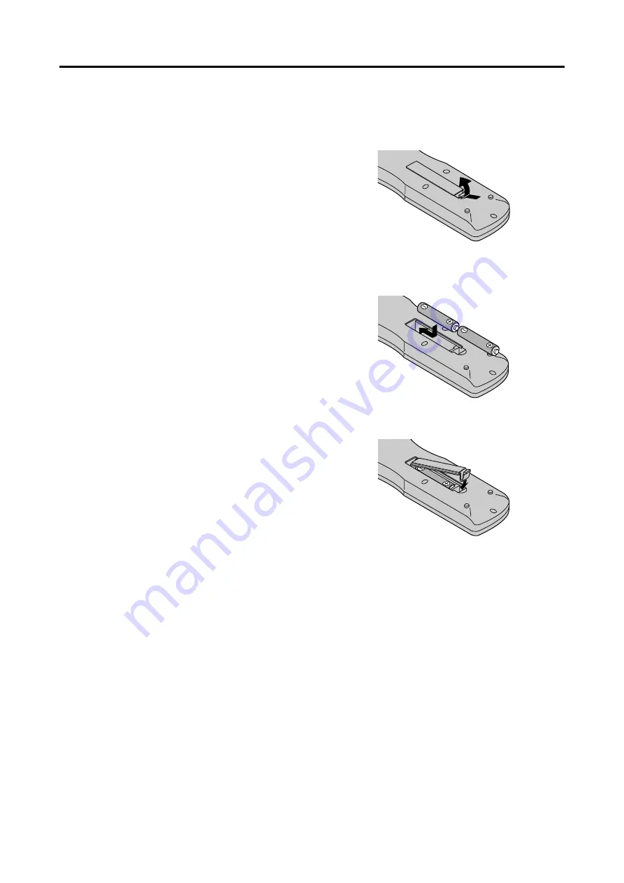
Battery Installation and Replacement

Insert the 2 “AAA” batteries, making sure to set them in
with the proper polarity.

1. Press and open the cover.

2. Align the batteries according to the (+) and (–) indication

inside the case.

3.Replace the cover.

!5

MULTI
Not functional for the models covered in this manual.

!6

SELECT
Not functional for the models covered in this manual.

!7

AUTO ADJUST
Press this button to adjust Fine Picture, Picture ADJ,
Position, and Contrast automatically, or to switch the
screen size to ZOOM mode automatically with the
superimposed caption displayed fully only when the
picture contains dark areas above and below the picture.

!8

ID SELECT
Set the ID number in the remote control. The remote
control can then be used only for a display with the
same ID number. When several displays are used
together they can be controlled individually.

!9

CLEAR
Clears the number set by the ID SELECT button.

@0

Remote control signal transmitter
Transmits the remote control signals.

@1

Remote Jack
Insert the plug of the remote cable (The 1/8 Stereo
Mini cable) here when using the supplied remote
control in the wired condition.

Summary of Contents for PlasmaSync 42VP4

Page 1: ...PlasmaSync Plasma Monitor User s Manual NEC Solutions America Inc...

Page 2: ...480P 1080I 720P and HDTV signal compatibility PCs VCRs Laser Disc and DVD player source compatibility AccuBlendscanconversionautomaticallyconverts SVGA XGA SXGA and UXGA signals to the panel s native...

Page 3: ...recaution This plasma monitor is designed and manufactured to provide long trouble free service No maintenance other than cleaning is required Please see the section Plasma monitor cleaning procedure...

Page 4: ...a Never use solvents such as alcohol or thinner to clean these surfaces 2 Clean plasma ventilation areas with a vacuum cleaner with a soft brush nozzle attachment 3 To ensure proper ventilation cleani...

Page 5: ...tives Certaines d entre elles ne produisent pas de lumi re ou restent allum es Pour des raisons de s curit et pour viter d endommager l appareil lire attentivement les instructions suivantes Pour vite...

Page 6: ...iffon doux et sec Ne jamais utiliser de solvents dutypealcooloudiluantpourlenettoyagedecessurfaces 2 Nettoyer les prises d a ration du plasma en proc dant l aide d une brosse poils doux fix e un aspir...

Page 7: ...color temperature 19 Adjusting the color to the desired level 19 Changing the Gamma Curve 20 Making the Low Tone adjustments 20 Adjusting the colors 21 Audio Settings Menu 21 Adjusting the treble bas...

Page 8: ...s own Be sure to use a stand or original mounting unit Wall mount unit Stand etc See the inside of the cover page For correct installation and mounting it is strongly recommended to use a trained auth...

Page 9: ...OSM mode Front View Part Names and Function MENU ENTER INPUTSELECT DOWN UP LEFT RIGHT EXIT VOLUME POWER STANDBY MENU ENTER INPUTSELECT DOWN UP LEFT RIGHT EXIT VOLUME POWER STANDBY 4 5 6 7 1 3 2 t LEF...

Page 10: ...t an analog RGB signal from a computer etc here This input can be used for Input or Output see page 10 H RGB3 DVI 24pin Connect a digital signal TMDS from a source with a DVI output see page 8 I EXTER...

Page 11: ...select VIDEO as the source VIDEO can also be selected using the INPUT SELECT button on the monitor t MENU ENTER Press this button to access the OSM controls Press this button during the display of th...

Page 12: ...cally or to switch the screen size to ZOOM mode automatically with the superimposed caption displayed fully only when the picture contains dark areas above and below the picture 8 ID SELECT Set the ID...

Page 13: ...cial light or if there is an obstacle between the sensor and the remote control Handling the remote control Do not drop or mishandle the remote control Do not get the remote control wet If the remote...

Page 14: ...ONO L AUDIO 3 R MONO L Cr Pr Y Cb Pb RGB 3 External Control IN OUT REMOTE VCR or Laser Disc Player Document Camera VIDEO 1 3 DVD Player IBM VGA or Compatibles To Mini D Sub 15 pin connector on the pla...

Page 15: ...ain unit NotethattheRGB3 DVI terminaldoesnotsupportanalog RGB input source Note 1 Input TMDS signals conforming to DVI standards The TMDS input corresponds to 1 link 2 To maintain display quality use...

Page 16: ...connection Bi directional DATA SDA Horizontal sync or Composite sync Vertical sync Data clock Pin No 1 2 3 4 5 6 7 8 9 10 11 12 13 14 15 1 2 3 4 5 6 7 8 9 10 11 12 13 14 15 16 20 19 18 17 21 22 23 24...

Page 17: ...68 60Hz signal A distribution amplifier is particularly recommended when using a 9 screen video wall From the second monitor onward connections require a BNC RCA conversion cable or connector a mini D...

Page 18: ...nges each time the DISPLAY button is pressed 2 If the button is not pressed for approximately three seconds the menu turns off DIGITAL ZOOM Digital zoom specifies the picture position and enlarges the...

Page 19: ...r has been set press the OFF TIMER button once 2 The remaining time is displayed then turns off after a few seconds 3 When five minutes remain the remaining time appears until it reaches zero OFF TIME...

Page 20: ...d in the horizontal direction squeezed images are expanded in the horizontal direction and displayed on the entire screen with correct linearity Normal images are expanded in the horizontal direction...

Page 21: ...f IBM Inc of the United States Note Do not allow the displayed in 4 3 mode for an extended period This can cause a phosphor burn in Wide Screen Operation with Computer Signals Switch to the wide scree...

Page 22: ...remote control to highlight the menu you wish to enter 3 Press the MENU ENTER button on the remote control to select a submenu or item PICTURE 1 2 EXIT CONTRAST BRIGHTNESS SHARPNESS COLOR TINT PICTURE...

Page 23: ...t values OFF Yes Main menu Sub menu Functions Default Reset AUDIO BASS Sets the bass Center Yes TREBLE Sets the treble Center Yes BALANCE Sets the left right balance Center Yes AUDIO INPUT1 3 Sets the...

Page 24: ...P OUT When set to ON the received signal will be looped out OFF Yes ID NUMBER Sets ID number for the display ALL Yes VIDEO WALL DIVIDER Creates a 2 2 or 3 3 video wall OFF Yes POSITION Sets the positi...

Page 25: ...mputer signal is connected Restoring the factory default settings Select DEFAULT under the PICTURE MODE settings Setting the picture mode according to the brightness of the room There are four picture...

Page 26: ...lasma display Example Setting HIGH Press the MENU ENTER button on the remote control to display the MAIN MENU on the screen then 1 Use the and buttons to select PICTURE then press the MENU ENTER butto...

Page 27: ...MA LOW TONE COLOR TUNE MID 3 AUTO SEL RETURN ADJ 4 Once the setting is completed Press the EXIT button to return to the main menu To delete the main menu press the EXIT button once more Information GA...

Page 28: ...adjustment CYAN Makes cyan s adjustment RESET Resets settings to the factory default value Use and buttons to select ON then press the MENU ENTER button Restoring the factory default settings Select...

Page 29: ...usting the Position Size Fine Picture Picture Adj The position of the image can be adjusted and flickering of the image can be corrected Example Adjusting the vertical position in the normal mode Pres...

Page 30: ...tores other settings to the factory defaults except for Auto Picture Option1 Settings Menu Setting the on screen menu This sets the position of the menu the display format horizontal or vertical etc E...

Page 31: ...INPUT SKIP ALL RESET NEXT PAGE CAN NOT ADJUST RGB RGB AUTO 1080B OFF OFF Setting a computer image to the correct RGB select screen With the computer image select the RGB Select mode for a moving imag...

Page 32: ...tching digital broadcasting 480P See page 41 for the details of the above settings Restoring the factory default settings Select ALL RESET under the OPTION1 menu Note that this also restores other set...

Page 33: ...n the main menu 1 2 then perform the following operations Press the MENU ENTER button on the remote control to display the MAIN MENU on the screen then 1 Use the and buttons to select OPTION2 then pre...

Page 34: ...CINEMA MODE ON Automatic discrimination of the image and projection in cinema mode OFF Cinema mode does not function Restoring the factory default settings Select ALL RESET under the OPTION1 menu Note...

Page 35: ...lines vertically every 3 minutes Perform Steps 1 3 of ORBITER then 4 Use the and buttons to select MANUAL then press the MENU ENTER button THE ORBITER screen appears 5 Adjust the items using the and...

Page 36: ...the minutes to 0M ON will be displayed SCREEN WIPER When this is set to ON a white vertical bar moves repeatedly from the left and of the screen to the right end at a constant speed Example Setting S...

Page 37: ...the following operations Press the MENU ENTER button on the remote control to display the MAIN MENU on the screen then 1 Use the and buttons to select OPTION2 then press the MENU ENTER button The OPTI...

Page 38: ...e Example Setting WEDNESDAY 22 05 Perform Steps 1 2 of TIMER then 3 Use the and buttons to select PRESENT TIME then press the MENU ENTER button The PRESENT TIME screen appears EXIT SEL RETURN PRESENT...

Page 39: ...the cursor with the DATE field that you wish to reset then press the CLEAR button To reset the data Align the cursor with the field ON OFF INPUT FUNCTION that you wish to reset then press the CLEAR bu...

Page 40: ...nu press the EXIT button once more Information CONTROL LOCK settings ON Disables the buttons on the front panel OFF Enables the buttons on the front panel Even when the CONTROL LOCK is set the POWER s...

Page 41: ...use multiple monitors to operate at the same time Example Setting 2 Set ADVANCED OSM to ON in the main menu 1 2 then perform the following operations Press the MENU ENTER button on the remote control...

Page 42: ...rmation Restoring the factory default settings Select ALL RESET under the OPTION1 menu Note that this also restores other settings to the factory defaults DIVIDER Set the 2 2 or 3 3 video wall Example...

Page 43: ...5 seconds the current setting is set and the previous screen reappears 6 Once the setting is completed Press the EXIT button to return to the VIDEO WALL screen Information IMAGE ADJUST settings These...

Page 44: ...econds the monitor will be turned on PLE LINK Use this function to set a uniform brightness for each display Turn on the AUTO ID before the following operations Example Setting ON Perform Steps 1 2 of...

Page 45: ...Setting the menu mode This allows you to access full menu items When P ON DELAY or PLE LINK is ON this won t be turned OFF Example Setting ON Press the MENU ENTER button on the remote control to disp...

Page 46: ...formats Different countries use different formats for video signals Set to the color system used in your current country AUTO The color systems are automatically identified and the format is set accor...

Page 47: ...80H 60H 47H 01H 01H 08H Video2 RCA DFH 80H 60H 47H 01H 02H 09H Video3 S Video DFH 80H 60H 47H 01H 03H 0AH DVD1 HD1 RCA DFH 80H 60H 47H 01H 05H 0CH DVD2 HD2 BNC DFH 80H 60H 47H 01H 06H 0DH RGB1 mini D...

Page 48: ...NEG NEG NEG POS NEG POS POS POS POS POS POS POS NEG NEG POS POS NEG POS POS POS POS POS NEG POS POS POS POS POS POS POS POS POS Sync on G Sync on G Sync on G Sync on G NEG NEG C Sync C Sync C Sync NE...

Page 49: ...onitor adapter D Sub 15 pin to your computer s video port 7 Other screen modes ZOOM and STADIUM are available as well NOTE While the input signals comply with the resolution listed in the table above...

Page 50: ...l s buttons are pressed The front panel buttons of the main unit do not function No sound or picture is produced Picture appears but no sound is produced Poor picture with VIDEO signal input Poor pict...

Page 51: ...articularly hot move the monitor to a cooler location and wait for the monitor to cool for 60 minutes If the problem persists contact your dealer 2 In the following case power off the monitor immediat...

Page 52: ...Low tone Color tune Audio Bass Treble Balance Audio input ImageAdjust Aspect mode V Position H Position V Height H Width Auto Picture Fine picture Picture adjustment Option1 OSM BNC Input D SubInput...

Page 53: ...46...

Page 54: ...47...

Page 55: ...ial technical adjustments set up including adjustment of user controls These costs are the responsibility of the NEC Solutions dealer from whom the product was purchased 3 Shipping charges HOW YOU CAN...

Page 56: ...49 Printed on recycled paper Printed in Japan 7S800941 NEC Solutions America Inc 1250 N Arlington Heights Road Suite 500 Itasca Illinois 60143 1248...

Reviews: