background image

English-18

BRIGHTNESS level set
for the monitor to use
when ambient lighting
level is low.

BRIGHTNESS level set for the
monitor to use when ambient
lighting level is high.

BRIGHTNESS range

IN DARK:

BRIGHTNESS level set for the monitor to use when ambient lighting level is low.

IN BRIGHT: BRIGHTNESS level set for the monitor to use when ambient lighting level is high.

Figure 1

dark

bright

room bright condition

Screen Brightness value by AMBIENT2 mode

Picture Mode

DVI, VGA, RGB/HV, DPORT
STANDARD

sRGB

AMBIENT1

AMBIENT2

HIGHBRIGHT

HDMI, DVD/HD1, DVD/HD2, SCART, VIDEO1, VIDEO2, S-VIDEO, TV*
STANDARD

CINEMA

AMBIENT1

AMBIENT2

HIGHBRIGHT

AMBIENT Mode

The brightness of the LCD screen can be set to increase or decrease depending on the amount of ambient light within the
room. If the room is bright, the monitor becomes correspondingly bright. If the room is dim, then the monitor will dim
accordingly. The purpose of this function is to make the viewing experience more comfortable to the eye in a variety of lighting
conditions.

NOTE:

When picture mode is set to AMBIENT1 or AMBIENT2, BRIGHTNESS, AUTO BRIGHTNESS and BRIGHTNESS in
SCREEN SAVER function are disabled.
Do not cover Ambient light sensor when you use AMBIENT1 or AMBIENT2 in PICTURE MODE.

AMBIENT parameter setting

PICTURE MODE in OSD, select AMBIENT1 or AMBIENT2 and set IN BRIGHT and IN DARK in each mode.

IN BRIGHT: This is the brightness level that the monitor will go up to when the ambient light level is highest.

IN DARK: This is the level of brightness that the monitor will go down to when the ambient light level is low.

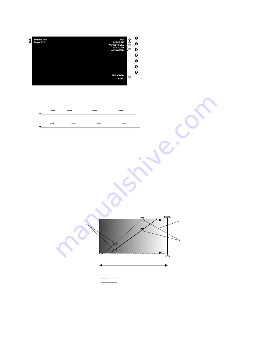
When the AMBIENT function is enabled the Brightness level of the screen changes automatically according to the lighting
conditions of the room (

Figure 1

).

IN DARK

IN BRIGHT

Information OSD

The Information OSD provides information such as: Monitor ID, Input Source, Picture Size, etc.
Press the DISPLAY button on the remote to bring up the Information OSD.

 ID number assigned to current monitor*

7

 ID number assigned monitor to be controlled via RS-232C*

8

 Input Name

 Audio input mode

 Picture aspect

 Input Signal Information

 Sub picture information

*7: “IR CONTROL” should be set “Primary” or “Secondary”.

*8: “IR CONTROL” should be set “Primary”.

*: The product you purchased may not have this feature.

Screen Brightness value by AMBIENT1 mode

Factory Setting

Summary of Contents for P401 - MultiSync - 40" LCD Flat Panel...

Page 1: ...User s Manual MultiSync P401 MultiSync P461 MultiSync P521 MultiSync P551...

Page 2: ...ON and OFF Modes English 16 Power Indicator English 17 Using Power Management English 17 Selecting a video source English 17 Picture Aspect English 17 Information OSD English 18 Picture Mode English 1...

Page 3: ...ection against harmful interference in a residential installation This equipment generates uses and can radiate radio frequency energy and if not installed and used in accordance with the instructions...

Page 4: ...ion Declaration of the Manufacturer We hereby certify that the color monitor MultiSync P401 L408TM MultiSync P461 L468TN MultiSync P521 L528N7 MultiSync P551 L559NL are in compliance with Council Dire...

Page 5: ...ot connect to a peripheral device with wiring that might have excessive voltage Connecting to a TV Cable distribution system should be grounded earthed in accordance with ANSI NFPA 70 the National Ele...

Page 6: ...l box and packing material to transport or ship the monitor 1 Type and number of power cords included will depend on the where the LCD monitor is to be shipped When more than one power cord is include...

Page 7: ...mation Make sure there is no gap between the monitor and the bracket Installation Mounting location The ceiling and wall must be strong enough to support the monitor and mounting accessories DO NOT in...

Page 8: ...ore moving the LCD Screw Holes Mounting accessories can be attached with the monitor in the face down position To avoid damaging the screen face place the protective sheet on the table underneath the...

Page 9: ...s control completely locks out access to all Control Key functions To activate the control key lock function press both and and hold down simultaneously for more than 3 seconds To resume user mode pre...

Page 10: ...g it to your monitor NOTE When you use Remote IN OUT IR CONTROL in OSD menu should be NORMAL Main Power Switch On Off switch to turn main power ON OFF AC IN connector Connects with the supplied power...

Page 11: ...AKER TERMINAL To output the audio signal from AUDIO 1 2 3 DPORT HDMI and TV jack Red terminal is plus Black terminal is minus Note This speaker terminal is for 15W 15W 8 ohm speaker Option board slot...

Page 12: ...20 EXIT button Returns to previous menu within OSD menu UP DOWN button Acts as button to move the highlighted area up or down to select adjustment items within OSD menu Small screen which adjusted PIP...

Page 13: ...s an object in the path Handling the remote control Do not subject to strong shock Do not allow water or other liquid to splash the remote control If the remote control gets wet wipe it dry immediatel...

Page 14: ...ote control batteries The remote control is powered by two 1 5V AA batteries To install or replace batteries NEC recommends the following battery use Place AA size batteries matching the and signs on...

Page 15: ...ke adjustments of the screen display position when necessary 10 Adjust the image See page 20 Make adjustments such as brightness or contrast when required 11 Recommended Adjustments To reduce the risk...

Page 16: ...VIDEO2 5BNC DVD HD2 5BNC VGA D Sub DVI DVI D RGB HV 5BNC DisplayPort Setting in Terminal Mode DVI MODE DVI HD RAW EXPAND 1 SCART ON BNC MODE VIDEO BNC MODE COMPONENT DVI MODE DVI PC BNC MODE RGB Inpu...

Page 17: ...forms to DVI standards Connecting a DVD Player with HDMI out Please use an HDMI cable with HDMI logo It may take a moment for the signal to appear PC DVI signals are not supported Connecting a Compute...

Page 18: ...rn green while powered on and will turn red or amber while powered off NOTE The Main Power Switch must be in the ON position in order to power up the monitor using the remote control or the Power Butt...

Page 19: ...d this function may not operate Selecting a video source To view a video source Use the input button to set VIDEO1 VIDEO2 S VIDEO Use the COLOR SYSTEM menu to set AUTO NTSC PAL SECAM PAL60 4 43NTSC ac...

Page 20: ...ENT1 or AMBIENT2 BRIGHTNESS AUTO BRIGHTNESS and BRIGHTNESS in SCREEN SAVER function are disabled Do not cover Ambient light sensor when you use AMBIENT1 or AMBIENT2 in PICTURE MODE AMBIENT parameter s...

Page 21: ...DOWN button to select Press INPUT button to decide Press UP or DOWN PLUS or MINUS button to select Press EXIT Control Panel OSD screen PICTURE MODE Goto Adjustment Select Return Close 70 50 50 50 50 5...

Page 22: ...by the LCD panel 2 2 Typical display gamma for use with a PC 2 4 Good for video TV DVD etc S GAMMA Special gamma for certain types of movies Raises the dark parts and lowers the light parts of the im...

Page 23: ...BASE ZOOM setting 0 V POS Vertical position Can be adjusted for each BASE ZOOM setting 0 ASPECT Selects picture aspect FULL NORMAL WIDE and ZOOM See page 17 FULL ADJUST RESET Resets the following set...

Page 24: ...aspect FULL NORMAL WIDE and ZOOM See page 17 FULL TEXT TICKER OFF MODE Enables Text Ticker and allows you to set Horizontal or Vertical direction POSITION Selects the location of the Text Ticker on th...

Page 25: ...mally using the remote controller PRIMARY Choose PRIMARY for the first monitor within an RS 232C daisy chain SECONDARY Choose SECONDARY for all subsequent monitors within an RS 232C daisy chain LOCK P...

Page 26: ...When connecting DVI the video card might not stop sending the digital data even though the image might have disappeared If this occurs the monitor will not switch into power management mode standby m...

Page 27: ...d monitor searches listed inputs only INPUT CHANGE Sets input change speed NORMAL NOTE When QUICK is selected picture may be distorted when signal input is changed This function should be chosen after...

Page 28: ...stays within the display area The whole image is displayed on the screen 120Hz P551 only When on this function provides a smoothing effect to video by automatically estimating and Depends on compensa...

Page 29: ...ains visible on the screen Unlike CRT monitors LCD monitors image persistence is not permanent but constant images being displayed for a long period of time should be avoided To alleviate image persis...

Page 30: ...le using the keypad to input the REMOTE CONTROL ID number 1 100 The REMOTE ID NUMBER should match the MONITOR ID number of the display to be controlled Choose 0 to simultaneously control all displays...

Page 31: ...control the SECONDARY monitor while aiming at the PRIMARY monitor The MENU OSD will appear on the selected target monitor NOTE If the ID No mode select OSD is showing press the DISPLAY button on the...

Page 32: ...ler for details In order to function the RS 232C OUT terminal can only be connected to another monitor of the same model Do not connect to other types of equipment To control monitor or multiple monit...

Page 33: ...ion for the web browser This device uses JavaScript and Cookies and the browser should be set to accept these functions The setting method will vary depending on the version of browser Please refer to...

Page 34: ...tor has been set to pd nec co jp access is gained to the network setting by specifying http pd nec co jp index html for the address or the entry column of the URL Example 2 When the IP address of the...

Page 35: ...ail This sets the user name for logging into the authentication server when authentication is required for the e mail transmission Up to 60 alphanumeric characters can be used This sets the password f...

Page 36: ...o your computer automatically optimizing display performance IPM Intelligent Power Manager System Provides innovative power saving methods that allow the monitor to shift to a lower power consumption...

Page 37: ...ould be connected Make certain the computer is not in a power saving mode touch the keyboard or mouse Check to see that the power indicator option in the OSD is set to ON RED LED on monitor is blinkin...

Page 38: ...EO Mini DIN 4 pin S VIDEO Y 1 0 Vp p 75 ohm C 0 286 Vp p 75 ohm NTSC 0 3 Vp p 75 ohm PAL SECAM NTSC PAL SECAM 4 43NTSC PAL60 Output Signal RGB HV BNC R G B H V Analog RGB 0 7 Vp p with 75 ohm terminat...

Page 39: ...VIDEO Mini DIN 4 pin S VIDEO Y 1 0 Vp p 75 ohm C 0 286 Vp p 75 ohm NTSC 0 3 Vp p 75 ohm PAL SECAM NTSC PAL SECAM 4 43NTSC PAL60 Output Signal RGB HV BNC R G B H V Analog RGB 0 7 Vp p with 75 ohm term...

Page 40: ...O Mini DIN 4 pin S VIDEO Y 1 0 Vp p 75 ohm C 0 286 Vp p 75 ohm NTSC 0 3 Vp p 75 ohm PAL SECAM NTSC PAL SECAM 4 43NTSC PAL60 Output Signal RGB HV BNC R G B H V Analog RGB 0 7 Vp p with 75 ohm terminate...

Page 41: ...S VIDEO Mini DIN 4 pin S VIDEO Y 1 0 Vp p 75 ohm C 0 286 Vp p 75 ohm NTSC 0 3 Vp p 75 ohm PAL SECAM NTSC PAL SECAM 4 43NTSC PAL60 Output Signal RGB HV BNC R G B H V Analog RGB 0 7 Vp p with 75 ohm ter...

Page 42: ...Name 1 connected to 7 8 2 RXD 3 TXD 4 connected to 6 5 GND 6 connected to 4 7 connected to 1 8 8 connected to 1 7 9 NC 1 6 5 9 D SUB 9P This LCD monitor uses RXD TXD and GND lines for RS 232C control...

Page 43: ...tp www necdisplay com in USA Energy Saving This monitor features an advanced energy saving capability When a VESA Display Power Management Signalling DPMS Standard signal is sent to the monitor the En...

Reviews: