background image

10

2. Installation and Connections

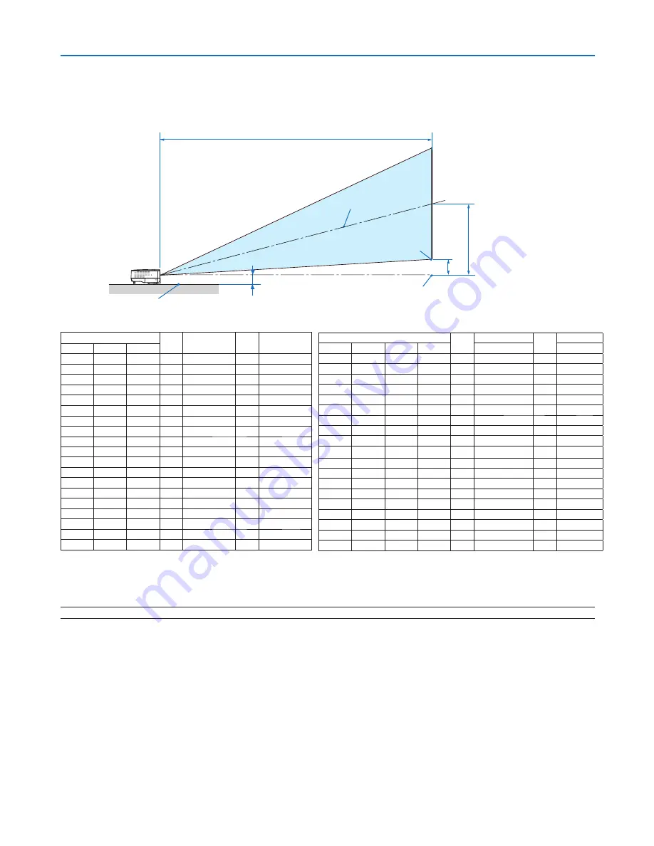
Throw Distance and Screen Size

The following shows the proper relative positions of the projector and screen. Refer to the table to determine the 
position of installation.

Distance Chart

NOTE: Distances may vary +/-5%.

C

D

B

Screen center

Lens center

Screen bottom

2.28"/58 mm

Projector bottom

Screen Size

B

C

D

α

Diagonal

Width

Height

wide -

tele

wide -

tele

inch

inch

inch

inch

inch

inch

degree

33 26 20 

13 

-

57 

-

12.6 

40 32 24 

15 

57 

-

69 

15.0 

-

12.5 

60 48 36 

23 

87 

-

104 

14.9 

-

12.4 

67 54 40 

26 

97 

-

117 

14.9 

-

12.4 

72 58 43 

28 

104 

-

126 

14.9 

-

12.4 

80 64 48 

31 

116 

-

140 

14.8 

-

12.4 

84 67 50 

32 

122 

-

147 

14.8 

-

12.4 

90 72 54 

35 

131 

-

158 

14.8 

-

12.4 

100 80  60 38 

145 

-

175 

14.8 

-

12.3 

120 96  72 46 

174 

-

210 

10 

14.8 

-

12.3 

150 120  90 58 

219 

-

263 

13 

14.7 

-

12.3 

180 144 108 69 

263 

-

317 

15 

14.7 

-

12.3 

200 160 120 77 

292 

-

352 

17 

14.7 

-

12.3 

220 176 132 84 

321 

-

387 

18 

14.7 

-

12.3 

240 192 144 92 

351 

-

422 

20 

14.7 

-

12.3 

260 208 156 

100 

380 

-

458 

22 

14.7 

-

12.3 

280 224 168 

107 

409 

-

493 

23 

14.7 

-

12.3 

300 240 180 

115 

439 

-

529 

25 

14.7 

-

12.3 

Screen Size

B

C

D

α

Diagonal Diagonal

Width

Height

wide

-

tele

wide - tele

inch

mm

mm

mm

mm

mm

mm

degree

33 838 671 503 

321 

-

1450 

70  - 12.6 

40 1016 813 610 

390 

1450 

-

1750 

85 

15.0 

- 12.5 

60 1524 

1219 914 

584 

2200 

-

2650 

127 

14.9 

- 12.4 

67 1702 

1361 

1021 

653 

2460 

-

2960 

142 

14.9 

- 12.4 

72 1829 

1463 

1097 

701 

2640 

-

3190 

153 

14.9 

- 12.4 

80 2032 

1626 

1219 

779 

2940 

-

3550 

170 

14.8 

- 12.4 

84 2134 

1707 

1280 

818 

3090 

-

3730 

178 

14.8 

- 12.4 

90 2286 

1829 

1372 

877 

3320 

-

4000 

191 

14.8 

- 12.4 

100 2540 2032 1524 

974 

3690 

-

4450 

212 

14.8 

- 12.3 

120 3048 2438 1829 

1169 

4430 

-

5340 

254 

14.8 

- 12.3 

150 3810 3048 2286 

1461 

5550 

-

6690 

318 

14.7 

- 12.3 

180 4572 3658 2743 

1753 

6670 

-

8040 

381 

14.7 

- 12.3 

200 5080 4064 3048 

1948 

7420 

-

8940 

424 

14.7 

- 12.3 

220 5588 4470 3353 

2143 

8160 

-

9830 

466 

14.7 

- 12.3 

240 6096 4877 3658 

2337 

8910 

- 10730 

509 

14.7 

- 12.3 

260 6604 5283 3962 

2532 

9650 

- 11630 

551 

14.7 

- 12.3 

280 7112 5690 4267 

2727 

10400 

- 12530 

593 

14.7 

- 12.3 

300 7620 6096 4572 

2922 

11140 

- 13430 

636 

14.7 

- 12.3 

B=Vertical distance between lens center and screen center
C=Throw distance
D=Vertical distance between lens center and bottom of screen(top of screen for ceiling application)

α

=Throw angle

Summary of Contents for NP60 - CEILING PLATE

Page 1: ...anual The projector s model name indicated on the projector s label is NP60 NP50 NP40 NP60G NP50G and NP40G respectively All six models are referred to as NP60 NP50 and NP40 throughout the user s manu...

Page 2: ...Other product and company names mentioned in this user s manual may be the trademarks or registered trade marks of their respective holders NOTES 1 The contents of this user s manual may not be repri...

Page 3: ...E PRONGS CAN BE FULLY INSERTED DOC Compliance Notice for Canada only This Class B digital apparatus meets all requirements of the Canadian Interference Causing Equipment Regula tions Machine Noise Inf...

Page 4: ...erent from that to which the receiver is connected Consult the dealer or an experienced radio TV technician for help For UK only In UK a BS approved power cable with moulded plug has a Black five Amps...

Page 5: ...ted by heat in front of the projector lens or a projector exhaust vent Doing so could lead to the object melting or getting your hands burned from the heat that is emitted from the light output and ex...

Page 6: ...message The lamp has reached the end of its usable life Please replace the lamp appears If you continue to use the lamp after the lamp has reached the end of its usable life the lamp bulb may shatter...

Page 7: ...ecting a Location 9 Throw Distance and Screen Size 10 Making Connections 12 Connecting Your PC or Macintosh Computer 12 Connecting Your DVD Player with Component Output 13 Connecting Your VCR or Laser...

Page 8: ...s Image Options 39 Menu Descriptions Functions Setup 41 Setup General 41 Setup Installation 42 Setup Options 44 Menu Descriptions Functions Information 45 Menu Descriptions Functions Reset 46 6 Mainte...

Page 9: ...cable US 7N080216 EU 7N080017 VGA signal cable 7N520054 CD ROM User s manual For North America only Registration card Limited warranty For Europe only Guarantee policy Quick Setup Guide Important Info...

Page 10: ...on Features you ll enjoy Auto Focus function When you turn on the power change the zoom or reposition the projector the Auto Focus function will work instantly The focus sensor on the projector detect...

Page 11: ...ke your time and do everything right the first time Take a few minutes now to review the user s manual This may save you time later on At the beginning of each section of the manual you ll find an ove...

Page 12: ...Adjustable Tilt Foot Button page 21 Adjustable Tilt Foot page 21 Remote Sensor page 8 Front Top AC Input Connect the supplied power cable s three pin plug here and plug the other end into an active wa...

Page 13: ...5 1 Introduction Bottom Lamp Cover page 48 Rear Feet page 21 Cooling Pump Cover page 50...

Page 14: ...MPUTER IN Component Input Connector Mini D Sub 15 Pin page 12 13 2 VIDEO IN Connector RCA page 14 3 S VIDEO IN Connector Mini DIN 4 Pin page 14 4 PC CONTROL Port Mini DIN 8 Pin page 60 Use this port t...

Page 15: ...LICK AUTO ADJ COMPUTER ASPECT HELP FREEZE PICTURE ENTER EXIT MENU UP FOCUS PAGE OFF POWER ON PIC MUTE DOWN 1 3 4 7 6 9 2 8 10 5 11 13 14 12 21 22 20 17 16 15 19 18 12 R CLICK MOUSE Button page 31 13 V...

Page 16: ...emote Control Battery Installation 1 Press firmly and slide the battery cover off 2 Install new batteries AAA En sure that you have the batteries polarity aligned correctly 3 Slip the cover back over...

Page 17: ...any oth er cables are disconnected before moving the projector When moving the projector or when it is not in use cover the lens with the lens cap To the wall outlet D i s t a n c e U n i t m i n c h...

Page 18: ...14 7 12 3 300 240 180 115 439 529 25 14 7 12 3 Screen Size B C D Diagonal Diagonal Width Height wide tele wide tele inch mm mm mm mm mm mm degree 33 838 671 503 321 1450 70 12 6 40 1016 813 610 390 1...

Page 19: ...F 40 C Eco mode selected automatically at 95 F to 104 F 35 C to 40 C Do not expose the projector to moisture dust or smoke This will harm the screen image Ensure that you have adequate ventilation ar...

Page 20: ...keys gets the external display to come on or off For example NEC laptops use Fn F3 while Dell laptops use Fn F8 key combinations to toggle through external display selections VGA signal cable supplied...

Page 21: ...and Connections NOTE Refer to your DVD player s owner s manual for more information about your DVD player s video output requirements Connecting Your DVD Player with Component Output DVD player Audio...

Page 22: ...yer S Video cable not supplied Video cable not supplied VCR Laser disc player Audio equipment Audio cable not supplied NOTE Refer to your VCR or laser disc player owner s manual for more information a...

Page 23: ...its stand by mode and the power indicator will glow orange CAUTION Do not try to touch the ventilation outlet on the right front when seen from the front as it can become heated while the projector i...

Page 24: ...inet or the POWER ON button on the remote control for 1 second The POWER indicator will turn to green and the projec tor will become ready to use TIP Turning on the projector will instantly cause the...

Page 25: ...anguage later Lan guage on page 41 NOTE Immediately after turning on the projector screen flicker may occur This is normal Wait 3 to 5 minutes until the lamp lighting is stabilized When the Lamp mode...

Page 26: ...ayed press the EXIT button to close the menu and start the operation 2 Press the SELECT button a few times quickly to select a sig nal you want to display Each time the SELECT button is pressed each s...

Page 27: ...each time the projector is turned on 1 Select Setup Options Default Source Select from the menu The Default Source Select screen will be displayed 2 Select a source as the default source and press th...

Page 28: ...hen use the Keystone feature for proper adjust ment page 25 Adjusting the Picture Size and Position About Auto Focus Just placing the projector on a flat level surface makes a fo cused image page 22 M...

Page 29: ...ton to lock the adjustable tilt foot There is approximately 10 degrees up of adjustment for the front of the projector Adjusting the height of a projected image or changing the projec tion angle will...

Page 30: ...d 5 5 m 216 5 it means that the focus sensor will not work correctly and that you need to use the FOCUS button to adjust the focus manually NOTE In some cases the Auto Focus may not work correctly or...

Page 31: ...gle during projection The left and right or horizontal keystone distortion is not available Place the projector so that the lens surface is parallel to the screen Also adjust the height to keep the pr...

Page 32: ...ector is placed within the effective focus range press ing and holding the FOCUS for a minimum of 2 seconds starts the Auto Focus function 2 Press the SELECT or button to adjust the focus 3 Press the...

Page 33: ...performing the Auto Keystone adjustment When the menu setting for Auto Keystone is turned off Adjusting with buttons on the cabinet 3 Projecting an Image Basic Operation 1 Press the SELECT or button...

Page 34: ...positioning vertical stripes banding or horizontal noise per form the Horizontal Vertical Clock or Phase function from the menu to optimize the image page 40 Performing the Horizontal Vertical Clock o...

Page 35: ...ower indicator will glow orange Immediately after turning on the projector and display ing an image you cannot turn off the projector for 60 seconds POWER STATUS LAMP POWER STATUS LAMP POWER STATUS LA...

Page 36: ...Cancel and press the ENTER button To change from Eco to Normal Go back to Step 2 and select Normal Repeat Step 3 Lamp Mode Description Status of LAMP indicator Normal Mode This is the default setting...

Page 37: ...mation screen will be displayed 6 Select Yes and press the ENTER button The Security function has been enabled To turn on the projector when Security is enabled When the Security function is enabled a...

Page 38: ...ton The Keyword confirmation screen will be displayed 4 Type in your keyword and press the ENTER button When the correct keyword is entered the Security function will be disabled NOTE If you forget yo...

Page 39: ...ndows 98 Me XP Windows 2000 or Mac OS X 10 0 0 or later operating system NOTE In Windows XP if the mouse cursor will not move correctly do the following Clear the Enhance pointer precision check box u...

Page 40: ...ion or online help supplied with your computer About Drag Mode By pressing the MOUSE L CLICK or R CLICK button for 2 or 3 seconds then releasing the drag mode is set and the drag operation can be perf...

Page 41: ...nu 5 Using On Screen Menu ENTER EXIT UP PAGE OFF POWER ON PIC MUTE DOWN FOCUS MENU ENTER EXIT MENU UP PAGE OFF POWER ON PIC MUTE DOWN FOCUS EXIT MENU UP PAGE OFF POWER ON PIC MUTE DOWN FOCUS ENTER Hig...

Page 42: ...cting items Solid triangle Solid triangle Indicates further choices are available A highlighted triangle indicates the item is ac tive Use the SELECT buttons to select the item For Selecting items Ret...

Page 43: ...reset Solid triangle Indicates further choices are available A highlighted triangle indicates the item is active Radio button Use this round button to select an option in a dialog box Slide bar Indica...

Page 44: ...Front Desktop Front Ceiling Rear Desktop Rear Ceiling Front Communication Speed 38400bps 4800bps 9600bps 19200bps 38400bps Control Panel Lock Off Off On Security Off Off On Menu Color Select Color Col...

Page 45: ...requency Video Type NTSC NTSC3 58 NTSC4 43 PAL PAL M PAL N PAL60 SECAM Sync Type Separate Sync Composite Sync Sync on Green Sync on Video Sync Polarity Scan Type Interlace Non Interlace Version Produc...

Page 46: ...Adjusting Color Temperature Color Temperature This option allows you to adjust the color temperature Use the SELECT or button to increase color temperature more blue to decrease color temperature mor...

Page 47: ...Yes Yes Yes Adjustable No Not adjustable Yes depending on the signal Reset The settings and adjustments for Picture will be returned to the factory settings with the exception of the follow ing Prese...

Page 48: ...rtical Clock and Phase Horizontal Vertical available for RGB signal only Adjusts the image location horizontally and vertically Clock available for RGB signal only Use this item to fine tune the compu...

Page 49: ...olor correction in applications where the screen material is not white The following 9 options are available Off Blackboard Blackboard Gray Light yellow Light green Light blue Sky blue Light rose and...

Page 50: ...400 bps Select the appropriate baud rate for your equipment to be connected depending on the equipment a lower baud rate may be recommended for long cable runs NOTE Your selected communication speed w...

Page 51: ...two color modes for menu color color and monochrome Selecting Menu Display Time Menu Display Time This option allows you to select how long the projector waits after the last touch of a button to tur...

Page 52: ...gnal received by any input Enabling Fan Speed Mode Fan Mode This option allows you to select two modes for fan speed Auto mode and High speed mode Auto The built in fans automatically run at a variabl...

Page 53: ...the video standard select the appropriate video standard from the menu This must be done for Video and S Video respectively TIP The projector automatically detects a component signal Lamp Life Remain...

Page 54: ...t except Language Background Communication Speed Security Lamp Life Re maining and Lamp Hours Used To reset the lamp usage time see Clearing Lamp Hour Meter Clear Lamp Hours below Clearing Lamp Hour M...

Page 55: ...n the focus sensor Keep finger prints off the focus sensor Leaving finger prints in the focus sensor might cause poor focus or short auto focus range Cleaning the Cabinet 1 Turn off the projector befo...

Page 56: ...c shock Do not break the glass on the lamp housing Keep finger prints off the glass surface on the lamp housing Leaving finger prints in the glass surface might cause an unwanted shadow and poor pictu...

Page 57: ...h the part as shown on the drawing and insert a new lamp housing until it is plugged into the socket CAUTION Do not use a lamp other than the NEC replacement lamp NP03LP NP60 or NP02LP NP50 NP40 Order...

Page 58: ...mp cover screw is not removable S VI DE O IN VI DE O IN N A C IN 2 Remove the cooling pump cover S VI DE O IN VI DE O IN N A C IN Contact area of the connector NOTE Keep the contact area of the connec...

Page 59: ...tor cannot turn on and the menu is not displayed If this happens press the HELP button on the remote control for 10 seconds to reset the lamp clock back to zero When the lamp time clock is reset to ze...

Page 60: ...on Note Off Normal Blinking light Red 1 cycle 0 5 sec On 2 5 sec Off Lamp cover error or lamp housing error Replace the lamp cover or lamp housing correctly 2 cycle 0 5 sec On 0 5 sec Off Temperature...

Page 61: ...next page Picture suddenly be comes dark When one of the following happens the Lamp mode automatically changes from Normal to Eco When there are no signals blue or black screen To return to the Norma...

Page 62: ...layed correctly Should this happen deactivate the notebook PC s LCD screen when the projector display is in use Each notebook PC has a different way of deactivate reactivate the local LCD screens as d...

Page 63: ...ojection Angle 14 7 15 0 wide 12 3 12 6 tele Electrical Inputs 1 VGA shared with component video Mini D Sub 15 Pin 1 S Video Mini DIN 4 Pin 1 Video RCA 1 PC Control Mini DIN 8 Pin Video Compatibility...

Page 64: ...to 40 C 20 to 80 humidity non condensing Storage Temperatures 14 F to 122 F 10 C to 50 C 20 to 80 hu midity non condensing Regulations For United States UL Approved UL 60950 1 Meets FCC Class B requir...

Page 65: ...UTO ADJ S VIDEO IN VIDEO IN COMPUTER IN PC CONTROL ON STAND BY FOCUS LAMP STATUS POWER SELECT AC IN 7 Appendix Cabinet Dimensions Lens center Unit mm inch 246 9 7 177 7 0 73 2 9 59 2 3 79 3 1 Lens cen...

Page 66: ...3 6 5 4 3 2 1 10 7 9 8 7 Appendix Pin No RGB Signal Analog YCbCr Signal 1 Red Cr 2 Green or Sync on Green Y 3 Blue Cb 4 Ground 5 Ground 6 Red Ground Cr Ground 7 Green Ground Y Ground 8 Blue Ground Cb...

Page 67: ...0 VESA 1280 1024 63 98 60 02 MAC 1280 1024 69 87 65 18 SXGA 1400 1050 60 00 VESA 1600 1200 75 00 60 02 VESA 1600 1200 87 50 70 00 VESA 1600 1200 93 75 75 00 HDTV 1080i 1920 1080 33 75 60 00 Interlace...

Page 68: ...10H 00H 00H 00H 12H PICTURE MUTE OFF 02H 11H 00H 00H 00H 13H Cable Connection Communication Protocol Baud rate 38400 bps Data length 8 bits Parity No parity Stop bit One bit X on off None Communicati...

Page 69: ...e sure repairs are needed also by referring to the Troubleshooting section in your user s manual This checklist below will help us solve your prob lem more efficiently Print this page and the next pag...

Page 70: ...Model number Length inch m Distribution amplifier Model number Switcher Model number Adapter Model number Projector PC DVD player Computer Manufacturer Model number Notebook PC Desktop Native resolut...

Page 71: ...t or movement by the customer or by improper handling by the customers 3 Problems or damage caused by improper usage or unwarrantable alterations or repairs by the customer 4 Problems or damage caused...

Page 72: ...1 465 85 2369 Fax Line 81 465 85 2393 Email Address support_pjweb nevt nec co jp WEB Address http www nec pj com Regions Covered Japan NEC Hong Kong Ltd Address 25 F The Metropolis Tower 10 Metropolis...

Page 73: ...riod I also confirm following information is correct Regards Application Sheet for TravelCare Service Program P 1 Country product purchased User s Company Name User s Company Address Phone No Fax No U...

Page 74: ...En duser is required to fill in Application Sheet Enduser needs to confirm the availability of the Service to NEC Authorized Service Stations 3 Loan Only For this service NEC Authorized Service Stati...

Reviews: