background image

59

4. Using Menus

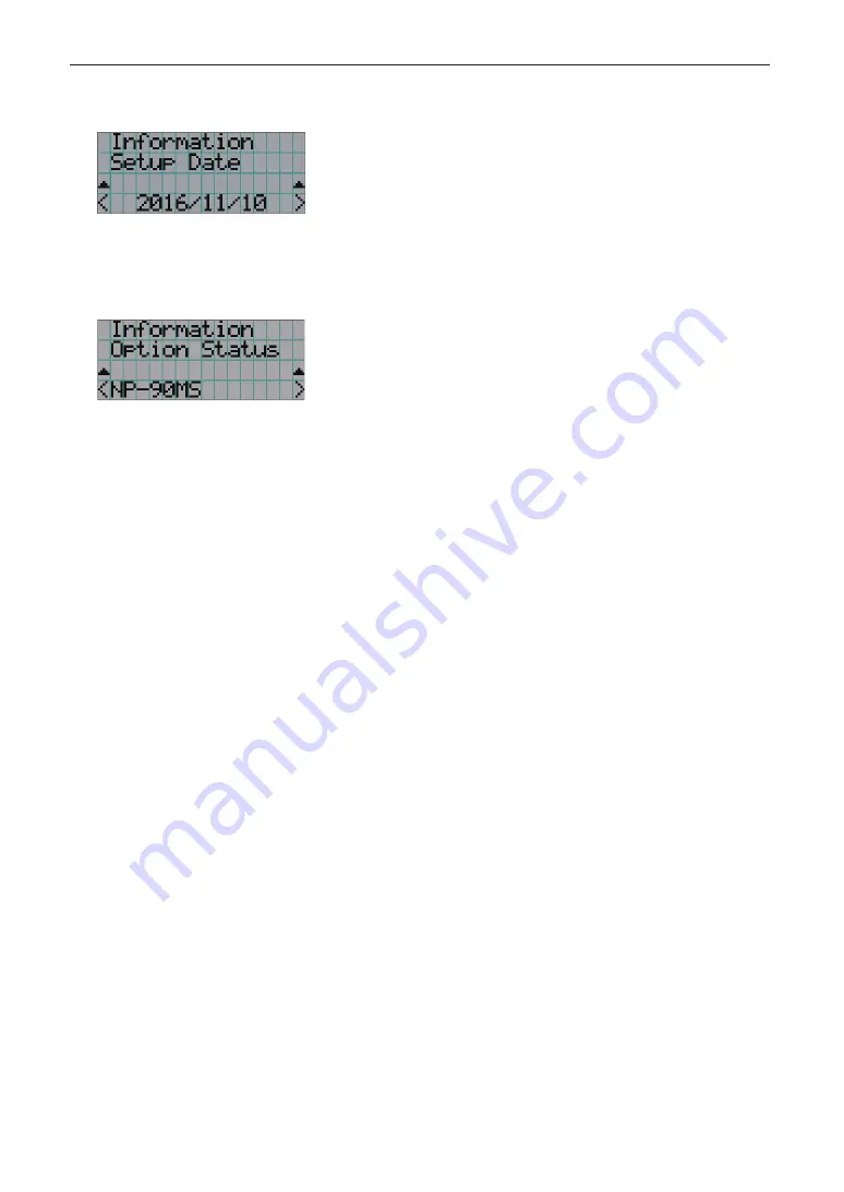
4-6-8. Setup Date

Displays the date when the projector was set up (starting date of the warranty period). 

  Displays the date when the projector was set up (starting date of the warranty period). 

4-6-9. Option Status

Displays the link status of the device mounted in slot on the projector. The device name is displayed in ( ) when the projector is in 
standby or when connection to the device cannot be confirmed. 

 Displays the link status of the device in slot.

  • NP-90MS: NP-90MS02
  • <Vendor Name> IMB: Media block
  • No Board: No device mounted

Summary of Contents for NC1700L

Page 1: ...User s Manual DLP Cinema Projector NC1700L Chiller Unit NP 17CU01 DLP Cinema Projector Model No NP NC1700L ...

Page 2: ... folder on the supplied CD ROM WARNING TO PREVENT FIRE OR SHOCK HAZARDS DO NOT EXPOSE THIS UNIT TO RAIN OR MOISTURE CAUTION TO REDUCE THE RISK OF ELECTRIC SHOCK DO NOT OPEN COVER NO USER SERVICEABLE PARTS INSIDE REFER SERVICING TO QUALIFIED SERVICE PERSONNEL This symbol warns the user that uninsulated voltage within the unit may have sufficient magnitude to cause electric shock Therefore it is dan...

Page 3: ...ANS Important Safeguards These safety instructions are to ensure the long life of your projector and to prevent fire and shock Please read them carefully and heed all warnings Installation 1 Do not point the projection beam toward other people or reflective objects 2 Consult your dealer for information about transporting and installing the projector Do not attempt to transport and install the proj...

Page 4: ...this requirement before attempting to use your projector 2 The power cable is not included with the projector Ask your dealer for the power cable to select and purchase Use a power cable that meets the standards and power supply voltage of the country where you are using the projector Refer to 2 2 Connecting the Power Cable page 30 for details on connecting the power cable Ask your dealer regardin...

Page 5: ...hen using a LAN cable For safety do not connect to the connector for peripheral device wiring that might have excessive Voltage 6 Do not try to touch the air outlets on the projector during normal projector operation as it is hot Important Information Cleaning 1 Turn off the projector and unplug the power cable before cleaning the cabinet or replacing the laser 2 During cleaning turn off the proje...

Page 6: ...rt branch for questions relating to unclear points malfunctions and repairs of the product In Europe Company Name Sharp NEC Display Solutions Europe GmbH Address LandshuterAllee12 14 D 80637Munich Germany Telephone 49 89 99699 0 Fax Line 49 89 99699 500 Email Address infomail nec displays com WEB Address https www sharpnecdisplays eu In North America Company Name Sharp NEC Display Solutions of Ame...

Page 7: ...d as RG3 of IEC62471 5 First edition 2015 Obey the laws and regulations of your country in relation to the installation and management of the device Internal laser output of the laser module Blue laser diodes Wave length 450 460 nm Output power 450 W Red laser diodes Wave length 636 642 nm Output power 100 W WARNING Always wear laser protection glasses that meet the following conditions while work...

Page 8: ...on Label B Label A Laser Aperture Class4 IEC 60825 1 2nd edition Hazard Warning Symbol Aperture Label Explanatory Label Label A Hazard Warning Symbol Explanatory Label and Aperture Label Label B Risk Group Lamp Safety Label ...

Page 9: ...9 Important Information Label E Label D Label C Label C Identification Label Certification Statement Label Label D Label E ...

Page 10: ...10 Chiller unit NP 17CU01 Label F Gas Label NP 17CU01 ID Label Important Information ...

Page 11: ...se duration CW Continuous Wave Modulation 23 192 Hz due to frame rate MPE Blue 450 460 nm Red 636 642 nm 260 J m2 NOHD 11 m Exposure duration 10 seconds 0 1 m Wide 0 15 m Tele Class 4 Class 3B 0 2 m Wide 0 6 m Tele 1 1 m Wide 1 6 m Tele 0 1 m Tele Class 3R Class 2 Class 1 NP 9LS12ZM1 0 1 m Wide 0 15 m Tele Class 4 Class 3B 0 2 m Wide 0 45 m Tele 2 45 m Wide 2 5 m Tele 0 1 m Tele Class 3R Class 2 C...

Page 12: ... 1 NP 9LS16ZM1 0 15 m Wide 0 15 m Tele Class 4 Class 3B 0 65 m Wide 1 0 m Tele 2 55 m Wide 2 6 m Tele 0 1 m Tele 0 1 m Wide Class 3R Class 2 Class 1 NP 9LS16Z1 0 2 m Wide 0 3 m Tele Class 4 Class 3B 0 6 m Wide 1 9 m Tele 2 6 m Wide 6 0 m Tele 0 1 m Tele 0 2 m Wide Class 3R Class 2 Class 1 NP 9LS20ZM1 Important Information ...

Page 13: ...s 1 NP 9LS40ZM1 NP 9LS40Z 0 15 m Wide 0 15 m Tele Class 4 Class 3B 0 65 m Wide 1 0 m Tele 2 55 m Wide 2 6 m Tele 0 1 m Tele 0 1 m Wide Class 3R Class 2 Class 1 NP 9LS16Z1 0 3 m Wide 0 3 m Tele Class 4 Class 3B 0 9 m Wide 1 9 m Tele 3 8 m Wide 6 0 m Tele 0 3 m Tele 0 3 m Wide Class 3R Class 2 Class 1 NP 9LS20Z1 Important Information ...

Page 14: ...ens Zoom Tele Wide Tele Wide NP 9LS12ZM1 15 7 22 1 NP 9LS12ZM1 8 5 12 2 NP 9LS13ZM1 13 3 20 2 NP 9LS13ZM1 7 1 11 0 NP 9LS16ZM1 10 1 16 6 NP 9LS16ZM1 5 4 9 0 NP 9LS16Z1 13 5 16 9 NP 9LS16Z1 7 1 9 1 NP 9LS20ZM1 7 2 13 2 NP 9LS20ZM1 3 8 7 1 NP 9LS20Z1 10 1 13 2 NP 9LS20Z1 5 4 7 1 NP 9LS40ZM1 NP 9LS40Z1 4 4 6 8 NP 9LS40ZM1 NP 9LS40Z1 2 3 3 6 H V V H Important Information ...

Page 15: ...eep over 2 m 2 5 m for USA distance at least between the floor surface and the RG3 area Lens HD m H m V m NP 9LS12ZM1 2 8 1 63 0 86 NP 9LS13ZM1 3 5 1 67 0 88 NP 9LS16ZM1 4 2 1 56 0 82 NP 9LS16Z1 3 7 1 81 0 96 NP 9LS20ZM1 4 7 1 21 0 64 NP 9LS20Z1 5 2 1 91 1 01 NP 9LS40Z NP 9LS40ZM1 10 0 1 58 0 83 When installed on a floor or a desktop Plan view Side view RG3 range RG3 range Vertical safety zone ove...

Page 16: ...en security measures if appropriate safety zone based on the installed lens is secured Periodically check the validity and keep these results Educate the administrator of the projector operators about safety before starting to operate the projector To use the projector Instruct the administrator of the projector operators to perform inspections before powering on the projector Including the safety...

Page 17: ...djusting the position and the size of projected screen 39 3 5 Preventing misoperations 43 3 6 Turning on off the light with the projector turned on 44 3 7 Turning your projector off 45 4 Using Menus 47 4 1 Basic operation with adjustment menus 47 4 2 Table of adjustment menus 52 4 3 Title Select 53 4 4 Configuration 54 4 5 Title Setup 56 4 6 Information 56 5 Maintenance of Your Projector 60 5 1 Cl...

Page 18: ...ving the degree of freedom of installation A wide variety of optional lenses sold separately are also available for the projector in order to support a wide variety of installation methods a lens is not mounted when the projector is shipped from the factory Equipped with easy to use functions 1 Lens memory function and light memory function that can be operated with one touch The projector is equi...

Page 19: ...n be assigned to the preset buttons 4 You can operate and configure the projector via a network from a PC You can operate and configure the projector via a network from a PC by using the separately supplied software Digital Cinema Communicator DCC for S2 Advanced Dust Protection A dust control shield is arranged between each DMD chip of R G and B and the spectroscopic condenser prism It prevents d...

Page 20: ...k the content of the accessories 1 2 1 Projector Projector Service door key x 2 CD ROM User s Manual Maintenance key for chiller unit Keys for administrator x 2 Power cable stopper Important Information Hose for chiller unit 2 m x 2 5 m x 2 Control cable 6m x 1 Retainer for Chiller unit ...

Page 21: ... Chiller unit NP 17CU01 Chiller unit NP 17CU01 TIP In the event that you did not receive all of the accessories outlined above or some are damaged contact your dealer distributor Differs slightly from the drawings in this manual but there is no problem in actual use ...

Page 22: ...tion 1 then your projector will enter a standby state 4 AC input Connects to the AC power cable The AC power cable is not an accessory Consult with your dealer distributor about the AC power cable 5 Power cable stopper Prevents the power plug from falling out from the projector 6 Switch for administrator The projector can be operated normally by inserting the administrator key vertically and turni...

Page 23: ...f the internal temperature and may cause a fire or malfunction 1 3 2 Rear of the projector 1 2 3 4 4 5 1 Air inlet The air inlet for cooling inside the projector Do not cover 2 Buzzer inside rear of projector The buzzer rings when the power is turned on or an error has occurred 3 Hose attachment port IN Connects to the attachment port OUT of the chiller unit using the hose for the chiller unit Req...

Page 24: ...mes of the Projector Parts 1 3 3 Bottom of the projector 1 2 2 1 Handle 4 locations Handles for moving the projector 2 Level adjusters in 4 positions In the ordinary installation you can adjust the projector inclination at 4 positions ...

Page 25: ... irradiation range earthquake fire etc In the emergency stop state the projector switches to the standby state 6 Temp Controller Displays the chiller unit temperature 7 Status display Displays operating state and error status of the chiller unit 8 Hole for AC power line The AC power line will be passed through into this hole And it will be connected inside in chiller unit The AC power line is not ...

Page 26: ...ojector from a PC via an RS 232C or for service personnel to set data for the projector Connect the projector and the PC with a commercially available RS 232C straight cable 5 3D terminal 3D D sub 15P The terminal for connecting a 3D image system to the projector See page 83 6 External control terminal GP I O D sub 37P The terminal for externally controlling the projector or connecting a 3D image ...

Page 27: ...g the KEY LOCK button for one second or longer while KEY LOCK is off locks the buttons Pressing the KEY LOCK button for one second or longer while KEY LOCK is on unlocks the buttons See page 43 NOTE KEY LOCK becomes automatically on if no control panel operation takes place in the standby state for 30 seconds by default See page 43 7 POWER button Press this button for more than three seconds to tu...

Page 28: ...0 titles input signals can be registered to this projector and any 16 titles from them can be assigned to the preset button Please request your dealer to register and change the titles of the buttons as required The preset button indicators show their assigned title or selection status See page 63 TIP To select a title allocated to one of the preset buttons use the following procedure To select a ...

Page 29: ... Setup the screen and projector and chiller unit Contact your dealer to carry out the setup Step 2 Connect the power cable to the projector See page 30 Step 3 Connect cables to the image input terminals See page 34 Connect cables to the various control terminals See page 34 2 Installation and Connection ...

Page 30: ...ground the equipment to ensure safety Use a power cable that meets the standards and power supply voltage of the country where you are using the projector page 75 and always connect the equipment to the ground If the ground is not connected it may cause electrical shocks When connecting the power cable plugs to the AC IN and the electrical outlet securely insert the plugs all the way in If the con...

Page 31: ...and Connection 1 Connect the AC power supply cable Connect the AC power supply cable to the projector AC input 2 Connect the power plug to the electrical outlet This completes the connection of the AC power supply cable ...

Page 32: ... to fix the power cable A loose contact of the power cable may cause a fire or electric shock Do not bundle the power cable Doing this could cause heat or a fire NOTE Do not clamp the power cable with other cables Doing so can generate noise which can affect adversely the signal cable Be careful not to insert the band inversely Once the band is attached it cannot be removed from the slot Attaching...

Page 33: ...m the power cable stopper 1 Push the clamper of the power cable stopper to unclasp it knob 2 Push the power cable clamper to open it wide enough to pull out the power cable knob clamper CAUTION The projector may become hot temporarily when the power is turned off or if the AC power is disconnected while the projector is projecting Take care when handling the projector ...

Page 34: ...ing the various control terminal For control your projector comes with such ports as the PC control terminal and the Ethernet port RJ 45 PC control terminal RS 232 Use this terminal when controlling the projector in serial connection from a PC LAN port LAN Use this port when controlling the projector in LAN connection from a PC Chiller unit control port Use this port to control the chiller unit fr...

Page 35: ...of projecting images Step 1 Turn on the power to the projector See page 36 Step 2 Select the title of input signal See page 38 Step 3 Adjust the position and size of the projected screen See page 39 Step 4 Turn off the power to the projector See page 45 ...

Page 36: ... projector and chiller unit is turn on Turning power off See page 45 1 Press the POWER button three seconds or longer Your projector is set in a standby state 2 Turn off the main power switch of the projector Your projector and chiller unit is turned off 1 Remove the lens cap 2 Turn ON the emergency stop switch AC power switch of chiller unit 3 Insert the administrator key vertically and turn it t...

Page 37: ... in cycles of 2 and changes to steady green light 90 seconds later The douser is closed until the screen glows light the DOUSER button indicator lights green When the douser is open the DOUSER button indicator turns off NOTE While your projector is on be sure to have the lens cap and glass protector cap removed from the lens Otherwise the lens cap or glass protector cap may get deformed due to a h...

Page 38: ...tor 2 Press the MENU button 3 Press the LEFT RIGHT button to display Title Select on the LCD screen At each press of the LEFT RIGHT buttons the display will cycle as Title Select Configuration Title Setup Information 4 Press the DOWN button The title of the input signal is displayed When you have made a wrong selection press the UP button A return will be made to the previous menu 5 Press the LEFT...

Page 39: ...ons select the test pattern according to 3 3 Selecting the title of input signal See page 38 2 Press the LEFT RIGHT button to display Title Select on the LCD screen 3 Press the DOWN button The title of the input signal is displayed 4 Press the LEFT RIGHT button to display TEST Pattern on the LCD screen 5 Press the DOWN button The LCD screen enters the mode where you can select a test pattern 6 Pre...

Page 40: ... Press the MENU button 2 Press the LEFT RIGHT button to display Configuration on the LCD screen 3 Press the DOWN button 4 Press the LEFT RIGHT button to display Lens Control on the LCD screen 5 Press the DOWN button The screen Lens Position to adjust the position of the projected screen is displayed 6 Press the UP DOWN LEFT RIGHT button The position of the projected screen moves in the selected di...

Page 41: ...tion of the projected screen is displayed 6 Press the ENTER button The screen to adjust the size and focus of the projected screen is displayed Press the ENTER button to switch the display between Lens Position and Focus Zoom adjustments ENTER button 7 Adjust the size and focus of the projected screen Press the UP DOWN button to adjust the focus Press the LEFT RIGHT button to adjust the size Focus...

Page 42: ...tically reduced This is called Thermal Protection Mode Down Light Power When the projector is in the Thermal Protection Mode the picture brightness decreases slightly To clear Thermal Protection Mode adjust the light output Consult with your dealer distributor for details 1 Press the LIGHT button The screen to adjust the light output is displayed 2 Press the LEFT RIGHT button to adjust the light o...

Page 43: ... Key Lock is enabled KEY LOCK becomes automatically on if no control panel operation takes place in the standby state for 30 seconds KEY LOCK becomes automatically on again even after KEY LOCK is turned off if no control panel operation takes place for 30 seconds When Auto Key Lock is disabled KEY LOCK becomes automatically on when the projector enters the standby state however it stays off after ...

Page 44: ... on while the LIGHT ON OFF button indicator is blinking If you operate the POWER button or LIGHT ON OFF button while the indicators are blinking the LCD screen displays the warning screen below The POWER button or LIGHT ON OFF button becomes operable when the amount of time remaining reaches 0 3 6 1 Turning off the light Press the LIGHT ON OFF button on the control panel for three seconds or longe...

Page 45: ...e LCD screen The cooling off time is 90 seconds When the cooling is finished the POWER button indicator turns off and the status indicator lights orange standby state KEY LOCK becomes automatically on if no control panel operation takes place in the standby state for 30 seconds by default Buttons on the control panel do not function while KEY LOCK is on See page 43 2 Wait till the projector enters...

Page 46: ... 232 USB REMOTE LAN 4 Turn OFF the emergency stop switch AC power switch of chiller unit 5 Turn off the AC power to the projector and chiller unit NOTE In the following instances do not turn off the main power switch or disconnect the AC power Doing so can damage the projector While projecting images While the fan is running after the power is turned off ...

Page 47: ...items and information on selected menus The meanings of symbols in the menu display screen are outlined below Indicates that there is a menu of a higher level Press the UP button to return to a menu one level above Indicates that there is a selected item or menu at the same level Press the LEFT RIGHT button to display other selected items or menus Indicates that there is a menu of a lower level Pr...

Page 48: ...etting Displays the selected title Displays the selected video input port When the power is turned off When you press the POWER button on the control panel of the projector for 3 or more seconds the projector starts cooling When cooling finishes the projector enters the standby mode The amount of time remaining for cooling is displayed as shown below during cooling When a button is pressed while t...

Page 49: ...ormation 3 Press the DOWN button The submenu Light Output of Information is displayed The menu item can be selected by pressing the ENTER button instead of the DOWN button To return to the previous state press the UP button or the EXIT button 4 Press the LEFT RIGHT button to select the submenu Version At each press of the LEFT RIGHT button the display will cycle as Light Output Lens Type Preset Bu...

Page 50: ...FT RIGHT button the display will cycle as Model Serial No Release Package Kernel U Boot System Files Cinema Firmware Cinema Data ICP Firmware ICP ConfigFile FMT FPGA Slave BIOS Slave Firmware Opt MCU Secure Processor Lens Laser Driver and each version information is displayed 8 Press the UP button several times At each press of the UP button the display will return to a menu one level above ...

Page 51: ... characters Characters can be entered by pressing each button as shown in the following table To delete a character during entry press the DOWN button Example of Entry To enter XGA for example use the following procedure 1 Press the 8 button three times V W X 2 Press the RIGHT button 3 Press the 3 button XG 4 Press the RIGHT button 5 Press the 1 button XGA Button Entered character 1 A B C 1 a b c ...

Page 52: ... Slot Configures the device installed in slot only when the projector is in standby mode Orientation Sets the projection method and cooling fan operating mode Lens Type Note Sets the type of lens supports or does not support the lens memory function attached to the projector 55 Lens Calibrate Note Performs calibration on lens that support the lens memory function only when the projector power is t...

Page 53: ...el and call them up directly using those buttons Request your dealer distributor for details on registering and changing titles Displays the currently selected item with asterisk Selects the title to be projected 4 3 2 Test Pattern Selects the test pattern to be projected Displays the currently selected item with asterisk Selects the test pattern to be projected OFF Alignment Cross Hatch Convergen...

Page 54: ...d screen Press the ENTER button to switch the display between Lens Position and Focus Zoom adjustments Press the EXIT button to return to a menu one level above Lens Position Adjusts the position of the projected screen The projected screen moves in the selected direction as you press the UP DOWN LEFT RIGHT button Focus Zoom Adjusts the size Zoom and focus Focus of the projected screen Press the U...

Page 55: ...en using a lens unit that does not support the lens memory function default value With Sensor Selected when using a lens unit that supports the lens memory function Lens Calibrate Performs calibration on lenses that support the lens memory function Once you have attached a lens that supports the lens memory function always execute calibration This menu item is available only when the projector pow...

Page 56: ...ror codes 4 6 1 Light Output Displays the value of the light source output setting Displays the current setting 4 6 2 Lens Type Displays the current lens type setting The lens type setting is configured from Lens Type in the Configuration Installation menu page 54 Displays the current lens type setting Without Sensor Using a lens unit that does not support the lens memory function With Sensor Usin...

Page 57: ...including standby mode while the lower row shows the usage time not including standby mode Light Displays the usage time of the light Light Strike Displays the number of times the light has been turned on Phosphor Display of the usage time of the phosphor and the value that is displayed is the amount of usage time remaining approximate Diffuser Display of the usage time of the diffuser and the val...

Page 58: ...inema Data ICP Firmware ICP ConfigFile FMT FPGA Slave BIOS Slave Firmware Opt MCU Secure Processor Lens Laser Driver IMB Displays the vendor name and version information about the media block IMB When the projector is in standby mode the vendor name is blank and the version information displays Displays the vendor name Displays the version information 4 6 7 IP Address Displays the IP address set i...

Page 59: ... starting date of the warranty period 4 6 9 Option Status Displays the link status of the device mounted in slot on the projector The device name is displayed in when the projector is in standby or when connection to the device cannot be confirmed Displays the link status of the device in slot NP 90MS NP 90MS02 Vendor Name IMB Media block No Board No device mounted ...

Page 60: ...iorate or peel off When removing dust on the ventilation opening suck it off using an adapter with a brush on a vacuum cleaner Never allow the cleaner without an adapter to come into direct contact or use a nozzles adapter in cleaning Clean the ventilation opening at regular intervals Dust if allowed to accumulate there may cause heating inside which leads to functional trouble The interval which ...

Page 61: ...ance of Your Projector 5 2 Cleaning the Lens Clean the lens the same way as with camera lens using a commercially available camera blower or cleaning paper for glasses Take care not to damage the lens when cleaning ...

Page 62: ...her The cooling fan settings need to be configured when using the projector at high elevations Please contact your dealer distributor for instructions Is the administrator key inserted The projector will not function unless the administrator key is inserted The image cannot be projected Check to see if the connected input has been selected Check to see if a cable is properly connected to the input...

Page 63: ...w when the buttons on the control panel or the STATUS indicator on the rear of the projector is lit or blink ing The projector also has a warning function that uses a buzzer KEY LOCK button POWER button DOUSER button LIGHT ON OFF button Preset buttons 6 2 1 Preset buttons Indicator condition Projector condition Note Off No title is assigned to the button Steady light A title is assigned to the but...

Page 64: ...When the sleep timer is activated Steady light Green The projector is turned on Orange The projector is in standby Note 1 Repeats 0 5 seconds on 0 5 seconds off Note 2 Repeats 0 5 seconds on 1 5 seconds off Note 3 Repeats 2 5 seconds on 0 5 seconds off 6 2 4 DOUSER button Indicator condition Projector condition Note Steady light Green The douser is closed Off The douser is opened 6 2 5 LIGHT ON OF...

Page 65: ...moment Red With buzzer Safety problem error An error message is displayed in the LCD screen Check the content of the error Red Without buzzer Error with possible image project under certain conditions Steady light Green The projector is turned on Orange The projector is in standby Red Error at a level with not affect on projection An error message is displayed in the LCD screen Check the content o...

Page 66: ... with a browser that uses a proxy server may not be possible depending on the type of proxy server and the setting method Although the type of proxy server will be a factor it is possible that items that have actually been set will not be displayed depending on the effectiveness of the cache and the contents set from a browser not be reflected in operation It is recommended that a proxy server not...

Page 67: ...clicking the same button one more time Focus G Focuses up the lens H Focuses down the lens Stops the focusing Focusing can also be stopped by clicking the same button one more time Mute Picture Click and the douser closes and the projected picture disappears Click once again and the picture will be projected again Projector Status Displays the condition of the projector Light Usage Displays the ho...

Page 68: ...taneously press the UP button and ENTER button The Save Info screen is displayed TIP If you press the EXIT button during operation operation is stopped and the display returns to the normal screen 3 Press the LEFT RIGHT button and select the log file writing period The items that can be selected are as follows Today Writes today s log files 7days Writes 7 days log files from today 30days Writes 30...

Page 69: ... displayed Press the ENTER button Press the ENTER button 5 Confirm the log file writing period press the LEFT RIGHT button to select Execute and press the ENTER button The log files of the specified period are written to the USB device When writing completes the following screen is displayed TIP If you select Cancel and press the ENTER button the writing of log files is stopped and the display ret...

Page 70: ...shows the model of projector Serial Number This shows the serial number of projector YYMMDDHHmm Shows the date time when written YY Year lower 2 digits MM Month 2 digits DD Date 2 digits HH Hour 2 digits mm Minute 2 digits For example if NC1700L log file is written at 14 05 on November 10 2016 it is saved with the NC1700L_abcd1234_1611101405 txt file name ...

Page 71: ...71 6 Appendix 6 5 Outline Drawing 6 5 1 Projector 846 930 725 86 700 590 314 326 84 149 206 Units mm ...

Page 72: ...72 6 Appendix 6 5 2 Chiller unit NP 17CU01 650 45 70 15 490 700 575 Units mm ...

Page 73: ...ess than 55 dB Installation Orientation Desktop front Desktop rear Net weight 68 5 kg Excluding lens Dimensions 700 mm W x 930 mm D x 326 mm H Does not include protruding portions includes foot Environment Operating temperature 10 to 35 C Operating humidity 10 to 85 non condensing Storage temperature 10 to 50 C Storage humidity 10 to 85 non condensing Operating altitude 0 to 3000 m 9800 feet 1600 ...

Page 74: ...lved 3 Children shall not play with the appliance Cleaning and user maintenance shall not be made by children without supervision 4 This appliance shall be installed in accordance with national wiring regulations 5 An all pole disconnection switch having a contact separation of at least 3mm in all poles should be connected in fixed wiring 6 If the supply cord is damaged it must be replaced by the ...

Page 75: ...acities as shown below Power supply voltage Projector input current Power cable current capacity AC 200 240V 10 7A MAX 250V 16A or higher Type of Power Cable Cable Plug Connector Use plugs cables and connectors that are suitable for the regulations of the country of installation as shown in the following table NOTE For users in North America Use a power cable no longer than 4 5m 14 76 ft according...

Page 76: ...03 VCTF 3 x 2 0mm IEC 320 C19 China Plug Cable Connector GB2099 RVV 300 500 GB17465 1 Connector Dimensions of the connector of the power cable are shown below 7 0 5 0 28 0 0 9 20 0 0 7 6 0 0 5 0 2 5 0 5 0 2 5 0 5 0 8 0 2 13 0 2 Unit mm R3 5 min 20 min ...

Page 77: ...ation 1 CD Carrier detection Not used N C 2 RXD Reception data Data transmission to an external device 3 TXD Transmission data Data reception from an external device 4 DTR Data Terminal ready Note Connection to 6 pins 5 GND Signal GND Signal GND 6 DSR Data set ready Note Connection to 4 pins 7 RTS Transmission request SYSTEM Hi Z Not used CINEMA Hi Z Used 8 CTS Transmission available SYSTEM Fixed ...

Page 78: ... IN 7 EXT_GPIN3 Control and Title Selection IN 26 EXT_GPIN3 Control and Title Selection IN 8 EXT_GPIN4 Control and Title Selection IN 27 EXT_GPIN4 Control and Title Selection IN 9 GPOUT1 External 3D L R Output Reference OUT 28 GPOUT1 External 3D L R Output Reference OUT 10 GPOUT2 system reserved OUT 29 GPOUT2 system reserved OUT 11 GPOUT3 system reserved OUT 30 GPOUT3 system reserved OUT 12 GPOUT4...

Page 79: ...er OFF OFF OFF ON ON Light source ON OFF ON OFF OFF Light source OFF OFF ON OFF ON Image douser ON OFF ON ON OFF Image douser OFF OFF ON ON ON System reserved used internally ON OFF OFF OFF Selects the title registered to the preset button 1 ON OFF OFF ON Selects the title registered to the preset button 2 ON OFF ON OFF Selects the title registered to the preset button 3 ON OFF ON ON Selects the t...

Page 80: ...at least 500 ms at least 500 ms approx 200 ms on off on off 8 27 5 24 6 25 7 26 Execute Select Preset Button time Example for turning the image douser Douser on Off at least 500 ms at least 500 ms approx 200 ms on off on off 5 24 7 26 6 25 8 27 Execute Image douser Douser ON time ...

Page 81: ...t least 500 ms at least 500 ms approx 200 ms on off on off 5 24 6 25 7 26 8 27 Execute Light source On time Example for turning the power off Off at least 500 ms at least 500 ms approx 200 ms on off on off 6 25 5 24 7 26 8 27 Execute Power OFF time ...

Page 82: ... and 16 35 EXT_GPOUT1 EXT_GPOUT4 as the default You can change the assigned functions Pin No Photo coupler ON OFF Function 9 28 ON OFF External 3D L R timing signal output ON OFF 10 29 System reserved used internally 11 30 System reserved used internally 12 31 ON OFF Internal 3D L R timing signal output ON OFF 13 32 ON OFF GPIO control status check ON GPIO control input is unavailable OFF GPIO con...

Page 83: ... projector 8 3D_INPUT_REFERENCE IN 3D L R timing signal Connects to the anode of the input diode of the photo coupler inside the projector 9 12V PWR Supplies power 12V to the 3D image system 10 3D_INPUT_REFERENCE IN 3D L R timing signal Connects to the cathode of the input diode of the photo coupler inside the projector 11 3D_DISPLAY_REFERENCE IN 3D L R display timing signal Connects to the anode ...

Page 84: ... 03 NP 9LS16Z1 Zoom lens 2 03 to 2 72 NP 9LS20Z1 Zoom lens 4 07 to 6 34 NP 9LS40Z Zoom lens 1 2 to 1 72 NP 9LS12ZM1 Zoom lens 1 33 to 2 1 NP 9LS13ZM1 Zoom lens 1 62 to 2 7 NP 9LS16ZM1 Zoom lens 2 09 to 3 9 NP 9LS20ZM1 Zoom lens 4 07 to 6 34 NP 9LS40ZM1 Integrated Media Server Integrated Media Server NP 90MS02 ...

Page 85: ... NEC Display Solutions Ltd 2016 Ver 2 2 21 ...

Reviews: