background image

English-10

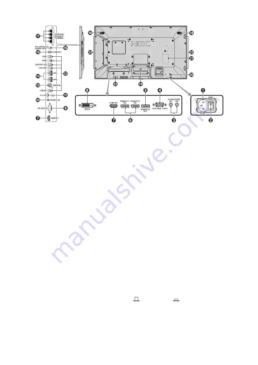
Terminal Panel

USB Upstream

 AC IN connector

Connects with the supplied power cord.

 Main Power Switch

On/Off switch to turn main power ON/OFF.

 AUDIO IN1/IN2

To input audio signal from external equipment such as a 
computer or player.

 VGA IN (mini D-Sub 15 pin)

To input analog RGB signals from a personal computer or 
from other RGB equipment. This input can be used with 
an RGB or YPbPr source. Please select signal type in 
TERMINAL SETTINGS. See page 37.

NOTE:

 When you use this connector for YPbPr, please use a 

suitable signal cable. If you have any questions, please ask 
your supplier.

 DisplayPort OUT

To output DisplayPort signals.
Outputs DisplayPort1 signal.

 DisplayPort IN1/IN2

To input DisplayPort signals.

 HDMI IN1/IN2

To input digital HDMI signals.


 DVI IN (DVI-D)

To input digital RGB signals from a computer or HDTV device 
having a digital RGB output.
* This connector does not support analog input.

 RS-232C IN (D-Sub 9 pin)

Connect RS-232C input from external equipment such as a 
computer in order to control RS-232C functions.

 REMOTE IN

Use the optional sensor unit by connecting it to your monitor.

NOTE:

 Do not use this connector unless specifi ed.

 microSD card slot

Insert a microSD memory card. To use Media player, please 
connect a microSD memory card to this port (See page 18).
To install the microSD card slot cover, please refer to 
“Installing microSD card slot cover” (See page 23).

 USB port

USB1: 

Downstream port (USB Type-A).


To connect USB devices.

USB2: 

Upstream port (USB Type-B).


To connect external equipment such as a   


computer. To control the monitor from connected  


external equipment, please use this port.

USB CM1 (2A): Power supply port.
USB CM2:  Service port. This port is for future software  
 upgrades.
USB MP: 

USB storage device port.


To use Media player, please connect USB  


storage device to this port (See page 18).


MP is an abbreviation of Media Player.

 VIDEO IN

To input a composite video signal.

 LAN port IN1/IN2 (RJ-45)

LAN connection. See page 47 and 50.

NOTE:

 Please give priority for use to LAN1.

 AUDIO OUT

To output the audio signal from the AUDIO IN1/IN2, 
DisplayPort and HDMI to an external device (stereo receiver, 
amplifi er, etc.).

NOTE:

 This connector is not a Headphone terminal.

 Internal/External speaker switch

: Internal speaker   

: External speaker.

NOTE:

 Please turn off the monitor’s main power when you 

use the Internal/External speaker switch.

Summary of Contents for MultiSync P404

Page 1: ...MultiSync P404 MultiSync V404 MultiSync P484 MultiSync V484 MultiSync P554 MultiSync V554 Please find your model name in the label on the backside of monitor Large Format Display User s Manual ...

Page 2: ...nglish 24 Media Player settings English 24 NETWORK OTHER SETTINGS English 25 Using SHARED SD card SETTINGS English 26 Using CONTENTS COPY English 27 Using Emergency contents English 27 Information OSD English 27 Picture Mode English 28 OSD On Screen Display Controls English 31 INPUT English 32 PICTURE English 32 AUDIO English 34 SCHEDULE English 35 MULTI INPUT English 36 OSD English 38 MULTI DISPL...

Page 3: ... separation between the equipment and receiver Connect the equipment into an outlet on a circuit different from that to which the receiver is connected Consult your dealer or an experienced radio TV technician for help If necessary the user should contact the dealer or an experienced radio television technician for additional suggestions The user may find the following booklet prepared by the Fede...

Page 4: ...been included Therefore it should be read carefully in order to avoid any problems CAUTION CAUTION Please use the power cord provided with this monitor in accordance with the table below If a power cord is not supplied with this equipment please contact your supplier For all other cases please use a power cord that matches the AC voltage of the power outlet and has been approved by and complies wi...

Page 5: ...once a year to remove dirt and dust When using a LAN cable do not connect to a peripheral device with wiring that might have excessive voltage Do not use the monitor in high temperature humid dusty or oily areas Do not use monitor under rapid temperature and humidity change condition and avoid cold air from air conditioning outlet directly as it may shorten the lifetime of the monitor or cause con...

Page 6: ...aning the Cabinet Unplug the power supply Gently wipe the cabinet with a soft cloth To clean the cabinet dampen the cloth with a neutral detergent and water wipe the cabinet and follow with a dry cloth NOTE DO NOT clean with benzene thinner alkaline detergent alcoholic system detergent glass cleaner wax polish cleaner soap powder or insecticide Rubber or vinyl should not be in contact with the cab...

Page 7: ...and washers in length If using screws longer than 10 12 mm check the depth of the hole Recommended Fasten Force 470 635N cm Bracket hole should be under φ 8 5 mm Prior to mounting inspect the installation location to ensure that it is strong enough to support the weight of the unit so that the unit will be safe from harm For detailed information refer to the instructions included with the mounting...

Page 8: ...ws for mounting DO NOT mount the unit to ceiling or to hanging fixtures Maintenance Periodically check for loose screws gaps distortions or other problems that may occur with the mounting equipment If a problem is detected please refer to qualified personnel for service Regularly check the mounting location for signs of damage or weakness that may occur over time Orientation When using the monitor...

Page 9: ...ace the monitor face down on the protective sheet NOTE Be sure to place the monitor on a flat and adequate space 3 Remove the attached slot cover by unscrewing the installed screws Figure 1 Figure 1 4 Insert the option board into the monitor and fix it with the removed screws Figure 2 NOTE Please contact your supplier for available option boards Do not apply excessive force to manipulate the optio...

Page 10: ...ure 3 Please adjust the pipe to the lines Figure 3 P554 V554 High Low P484 V484 High Low P404 V404 High Low Pipe Adjust the pipe to a line 2 Please install the stand pole and the pipe with included screws Please screw the two screw holes at the pipe Figure 4 Pipe Figure 4 Stand pole NOTE Installing the monitor at the wrong height can cause tipping Please install your monitor at proper height 5 Ven...

Page 11: ...nu when the OSD menu is turned off Acts as button to move the highlighted area down to select adjustment items within the OSD menu OSD is an abbreviation of On Screen Display MENU EXIT button MENU EXIT Activates the OSD menu when the OSD menu is turned off Acts as EXIT button within the OSD to move to previous menu Remote control sensor and Power Indicator Receives the signal from the remote contr...

Page 12: ...it by connecting it to your monitor NOTE Do not use this connector unless specified microSD card slot Insert a microSD memory card To use Media player please connect a microSD memory card to this port See page 18 To install the microSD card slot cover please refer to Installing microSD card slot cover See page 23 USB port USB1 Downstream port USB Type A To connect USB devices USB2 Upstream port US...

Page 13: ...lot 2 type accessory is available Please contact your supplier for detailed information NOTE Please contact your supplier for available option board Kensington Lock For security and theft prevention Rating label Intelligent wireless data sensor Sensor for wireless communication of monitor for information and settings Option speaker mounting hole NOTE Please contact your supplier for available opti...

Page 14: ...as set button when you made selection POINT ZOOM When OSD is not shown this button acts as point zoom button VOLUME UP DOWN button VOL Increases or decreases audio output level CH ZOOM UP DOWN button CH ZOOM 1 Increases or decreases POINT ZOOM level Please refer to POINT ZOOM See page 58 GUIDE button 1 MUTE button Turns on off the mute function PICTURE MODE button Selects picture mode HIGHBRIGHT S...

Page 15: ...Selects active picture frame aspect NOTE Enable to change each multi picture size by pressing SET POINT ZOOM button during multi picture mode REMOTE ID button Activates the REMOTE ID function See page 46 MTS button 1 button 1 Activates closed captioning NOTE VIDEO input only 1 This button s action depends on which option board you are using Refer to the option board s user s manual for further inf...

Page 16: ...onitor when it was packaged 2 Install the remote control batteries The remote control is powered by two 1 5V AAA batteries To install or replace batteries A Press and slide to open the cover B Align the batteries according to the and indications inside the case C Replace the cover CAUTION Incorrect usage of batteries can result in leaks or bursting NEC recommends the following battery use Place AA...

Page 17: ...ired 8 Adjust the screen See pages 33 and 34 Make adjustments to the image position if necessary 9 Adjust the image See page 32 and 33 Make adjustments such as backlight or contrast when required 10 Recommended Adjustments To reduce the risk of the Image Persistence please adjust the following items based on the application being used SCREEN SAVER SIDE BORDER COLOR See page 40 DATE TIME See page 3...

Page 18: ...or DVD player Multiple monitors that are daisy chained have a limit to the connectable monitors 1 The device connected to USB2 can control the device connected to USB1 Connected equipment Connecting terminal Setting in TERMINAL SETTINGS Input signal name Connecting audio terminal Input button in remote control AV DVI DVI MODE DVI HD DVI IN1 IN2 DVI HDMI IN1 VIDEO LEVEL RAW EXPAND 2 HDMI1 HDMI1 HDM...

Page 19: ...osh series computer user s manual for more information about your computer s video output requirements and any special identification or configuration your monitor s image and monitor may require Input TMDS signals conforming to DVI standards To maintain the image reproduction quality use a cable that conforms to DVI standards Connecting a Player or Computer with HDMI Please use an HDMI cable with...

Page 20: ...puter BIOS OS or device the USB function may not be working In this case please check user s manual of your computer or device or contact your supplier for detailed information Before turning off the main power switch of the monitor or shutting down Windows please turn off the USB function and remove the USB cable from the monitor You may lose data when the computer crashes It may take a few secon...

Page 21: ... monitor power indicator will turn blue while powered on NOTE The Main Power switch must be in the ON position in order to power up the monitor using the remote control or the Power button Main Power Switch OFF ON Power Button Using the remote control POWER ON button ...

Page 22: ...h an option board INPUT DETECT is set to a setting except for NONE USB POWER is set to ON DisplayPort is set to MST Glowing amber The monitor has been past a certain amount of time with network signal input no AV signal input which you set Blinking amber The monitor has been past a certain amount of time with network signal input no AV signal input which you set Glowing red Turn off the monitor by...

Page 23: ...the viewer 1 to 4 shared folders can be set When the connection to the shared folder fails an error message is displayed and an x is displayed in the folder icon Carry out the following checks in this case Is the name of the destination folder correct Is the destination folder set for sharing Have access rights been set in the destination folder Are there any displayable files saved in the destina...

Page 24: ...edia package Visit our web site for downloading authoring software and its user s manual NOTE Contents schedule works based on the DATE TIME setting of the monitor If you change the DATE TIME setting while a content is playing please finish playing the contents once When starts displaying the contents again the contents schedule follows changed DATE TIME setting Date display format is changing wha...

Page 25: ...roSD memory card from the microSD card slot press the center of the microSD memory card then take it out File display screen The files can be displayed using either icons or thumbnails in the Media Player Icon display RETURN Goes back one subsequent level higher PAGE UP Displays a list of the previous files PAGE DOWN Displays a list of the next files SETTINGS Displays the setting screen THUMBNAILS...

Page 26: ...PLAY END SCREEN Selects a setting after slideshow is down BLACK SCREEN After slideshow has been done black is displayed on the screen FILE LIST Gets back to the file list screen SAVE LAST SCREEN The last slideshow image is kept on the screen MEDIA PACKAGE Menu Function SCREEN SIZE Selects ACTUAL SIZE or BEST FIT INTERLOCK POWER Check the check box to enable the monitor to be turned ON or STANDBY b...

Page 27: ... in the SHARED SD CARD SETTINGS If OK is not pressed settings that you set are not activated SHARED FOLDER SETTINGS Folders saved in a computer which is on a network can be copied to the connected microSD memory card by controlling the monitor Menu Function ENABLE Check the checkbox to enable SHARED FOLDER SETTINGS SHARED FOLDER Set an IP address which a copied data to be saved USER NAME Set USER ...

Page 28: ...ts Setting procedure 1 Open Monitor LAN control of the connected monitor then select SD CARD VIEWER 2 Select SEARCH to display monitor ID ADDRESS which monitor s network is on the same network as the monitor 3 Select connected monitor s IP ADDRESS to the monitor 4 Enable upload delete and sort files that are saved in microSD memory card connected to the monitor Function 1 SELECT UPLOAD Press SELEC...

Page 29: ... storage capacity is not enough to copy selected folders When contents copy has occurred previous data that was saved in the microSD memory card is deleted Only devices connected to the monitor are shown When the monitor is copying a folder the LED indicator blinks in red When the monitor is in this condition do not eject a microSD memory card from the monitor or do not turn off the monitor s main...

Page 30: ...e used for the Internet Windows operating systems and digital cameras Recommended setting for general color management Adobe RGB SIM Provides a standard color space used in high end graphics applications such as professional digital still cameras and imaging eciRGB_v2 SIM Provides a color space profile recommended by ECI The European Color Initiative DCI SIM Color setting for digital cinema REC Bt...

Page 31: ...rate the view of those with a color vision deficiency It is not their actual view The simulation is a reproduction of those with a strong color vision mode of type P type D or type T People with a slight color vision deficiency will experience little to no difference compared to those with normal color vision UNIFORMITY 1 This function electronically compensates the slight variations in the white ...

Page 32: ...M2 HIGHBRIGHT For VGA YPbYr VIDEO MP STANDARD CINEMA CUSTOM1 CUSTOM2 HIGHBRIGHT PRESET types PRESET PURPOSE HIGH BRIGHT Highest brightness setting STANDARD Standard setting sRGB The standard color space used for the Internet Windows operating systems and digital cameras Recommended setting for general color management CINEMA A setting that boosts dark tones best suited for movies CUSTOM Activates ...

Page 33: ... x 0 683 y 0 306 GREEN x y x 0 191 y 0 709 BLUE x y x 0 153 y 0 044 COLORVISIONEMU OFF UNIFORMITY OFF METAMERISM ON OFF COLORCONTROL R 0 Y 0 G 0 C 0 B 0 M 0 Goto Adjustment Select Return Close MULTI INPUT OPTION Input source Main Menu Icons Main Menu Item Sub Menu Key Guide Adjustment Settings Remote Control Press UP or DOWN button to select sub menu Press SET POINT ZOOM Press UP or DOWN PLUS or M...

Page 34: ...movies Raises the dark parts and lowers the light parts of the image S Curve DICOM SIM DICOM GSDF curve simulated for LCD type PROGRAMMABLE1 2 3 A programmable gamma curve can be loaded using optional NEC software COLOR 2 COLOR Adjusts the color depth of the screen Press or to adjust COLOR TEMPERATURE 1 Adjusts the color temperature of the entire screen A low color temperature will result in a red...

Page 35: ...before IMAGE FLIP then start to IMAGE FLIP When the ASPECT is DYNAMIC or ZOOM the image will be changed to FULL image before TILE MATRIX then start to TILE MATRIX After TILE MATRIX the ASPECT will be returned previous ASPECT or set ASPECT during TILE MATRIX If you change H POSITION and V POSITION settings with a reduced image the image would not be changed If SCREEN SAVER is set the ASPECT setting...

Page 36: ...played clearly but it makes brightness unstable due to the wide gap of contrast variation ROTATION Shows the inverse image right left up down or rotation Press or to select NOTE This function is not available when MOTION in SCREEN SAVER is ON IMAGE FLIP NOTE When the ASPECT is set to DYNAMIC the image will be changed to FULL image before ROTATE starts then ROTATE will start to work When selecting ...

Page 37: ...IME Set schedule operation time If there is no specific time for the schedule set INPUT Set input signal for the schedule To keep the input signal which was chosen before schedule is operating set When you set INPUT please select ON at POWER PIC MODE Set picture mode for the schedule To keep the picture mode which was chosen before schedule is operating set When you set PIC MODE please select ON a...

Page 38: ...VE When MULTI PICTURE is OFF PICTURE 1 is the Active Picture When MULTI PICTURE is ON sets Active Picture NOTE This function depends on MULTI PICTURE setting ACTIVE FRAME The active picture is shown within a red frame INPUT SELECT 1 2 3 Selects the Multi Picture input Press the button or button to select the input NOTE This function is not available when MULTI PICTURE is OFF When changing input si...

Page 39: ...I D equipment which is connected to the DVI input Select DVI HD when a DVD player or computer equipment is connected which requires HDCP authentication Select DVI PC when computer equipment is connected which does not requires HDCP authentication VGA MODE Selects RGB or YPbPr for VGA input SYNC TYPE Selects a type of sync signal of VGA RGB AUTO Automatically identifies received sync signal type H ...

Page 40: ...closed captioning NOTE This function is released if the following function is activated MULTI PICTURE MODE TEXT TICKER PORTRAIT in OSD ROTATION TILE MATRIX SCREEN SAVER STILL POINT ZOOM SUPER in INPUT CHANGE RESET Resets the following settings within the OSD menu back to factory setting OSD TIME OSD POSITION INFORMATION OSD OSD TRANSPARENCY CLOSED CAPTION MULTI DISPLAY AUTO TILE MATRIX SETUP TILE ...

Page 41: ...TING When SET is selected AUTO ID IP SETTING window is shown Do not connect network devices between the monitors connected with LAN SETTING ITEM Select an item from MONITOR ID IP ADDRESS and ID and IP MONITOR ID When YES is set monitor ID numbers are set automatically to the all monitors IP ADDRESS Set the first octet to the third octet at BASE ADDRESS The fourth octet is automatically set from 1 ...

Page 42: ...mote control The side borders will become brighter By pressing the button the side borders will become darker Background color of the media player window is also changed POWER ON DELAY Adjusts the delay time between being in standby mode and entering power on mode DELAY TIME POWER ON DELAY can be set between 0 and 50 seconds LINK TO ID When ON selected delay time is linked with Monitor ID It takes...

Page 43: ... unlocked The unselected buttons are locked When LOCK is selected all INPUT buttons are locked CHANNEL To lock channel buttons on the remote control select it to LOCK then press ACTIVE channel CH ZOOM button and button are locked KEY LOCK SETTINGS Prevents the monitor from being controlled by buttons of the monitor When ACTIVATE is selected all the settings are activated NOTE KEY LOCK SETTINGS is ...

Page 44: ...nt lighting level is low BACKLIGHT level set for the monitor to use when ambient lighting level is high BACKLIGHT range dark bright room bright condition Screen Backlight value by MODE2 IN DARK IN BRIGHT Screen Backlight value by MODE1 Factory Setting BACKLIGHT range when set to MAX LIMIT MAX LIMIT BACKLIGHT level is limited to your set level IN DARK BACKLIGHT level set for the monitor to use when...

Page 45: ...ically To retry the SEARCH DEVICE set it to YES again After detected HDMI CEC devices you can switch the device input by selecting the device RESET Resets all the settings within the CONTROL menu back to factory setting except for LAN CHANGE PASSWORD SECURITY PING and INTELLI WIRELESS DATA OPTION OPTION POWER Allows the monitor to supply power to an Option board slot during power save mode or stan...

Page 46: ...isplay the estimated carbon usage information in kg CO2 This is the arithmetic estimation not actual measurement value This estimation is based without any options FIRMWARE Displays firmware version that is installed to the monitor MAC ADDRESS Displays the MAC ADDRESS FACTORY RESET All items are returned to factory shipment state NOTE You can reset all items in all daisy chained monitors Please be...

Page 47: ...isible on the screen Unlike CRT monitors LCD monitors image persistence is not permanent but constant images being displayed for a long period of time should be avoided To alleviate image persistence turn off the monitor s main power or set it to standby for as long as the previous image was displayed For example if an image was on the monitor for one hour and a residual image remains the monitor ...

Page 48: ...age 39 Point the remote control towards the remote sensor of the desired monitor and press the REMOTE ID SET button The MONITOR ID number is shown on the screen when your remote control is in ID mode Use the remote control to operate a monitor that has a specific MONITOR ID number assigned to it 1 Set the MONITOR ID number for the monitor See page 39 The MONITOR ID number can range from 1 100 This...

Page 49: ...ve a limit to the connectable monitors Please execute AUTO ID see page 39 before manually specifying the ID number or control by the specified ID number Main Monitor Sub Monitors Connector Connector IN OUT IN OUT RS 232C LAN2 LAN1 LAN2 REMOTE IN LAN1 Connection LAN Cable MultiSync MultiSync LAN Cable MultiSync LAN1 LAN2 LAN1 LAN2 Multiple Monitors Connection ...

Page 50: ...mes com port does not work properly When controlling the monitor connected with RS 232C cable please refer to the Control command diagram See page 56 or see the External_Control pdf file on the CD ROM supplied with the monitor RS 232C Cable Computer RS 232C MultiSync NOTE If your computer is equipped only with a 25 pin serial port connector a 25 pin serial port adapter is required Contact your sup...

Page 51: ...LCD monitor uses RXD TXD and GND lines for RS 232C control The reverse type cable null modem cable not include should be used for RS 232C control 2 PIN ASSIGNMENT RS 232C input output 1 6 5 9 D SUB 9P Monitor side Pin No Name 1 NC 2 RXD 3 TXD 4 NC 5 GND 6 NC 7 NC 8 NC 9 NC This LCD monitor uses RXD TXD and GND lines for RS 232C control ...

Page 52: ... refer to the help files and the other information provided in your software Access is gained to the HTTP server function by starting the Web browser on the computer via the network connected to the monitor and entering the following URL Network Setting http the Monitor s IP address index html HINT The default IP address is assigned automatically to the monitor The exclusive application can be dow...

Page 53: ... monitor has been configured in the HOSTS file of the computer being used you can then access the network settings of the monitor via this host name by using a compatible browser Example 1 When the host name of the monitor has been set to pd nec co jp access is gained to the network setting by specifying http pd nec co jp index html for the address or the entry column of the URL Example 2 When the...

Page 54: ...hen MANUAL is selected for IP SETTING NOTE Set as 0 0 0 0 to delete the setting DNS Set for IP ADDRESS setting of DNS server AUTO The DNS server which is connected with the monitor will automatically assign his IP address MANUAL Manually enter the IP address of the DNS server which is connected with the monitor PRIMARY DNS Enter the primary DNS server settings of the network connected with the mon...

Page 55: ...our settings are correct NOTE If you execute a test you may not receive an Alert email Should this happen check whether the network settings are correct If you entered an incorrect address in a test you may not receive an Alert email Should this happen check whether the Recipient s Address is correct HINT For the control command diagram please see the file External_Control pdf on the CD ROM suppli...

Page 56: ...ff for the detection from AMX Device Discovery when connecting to a network supported by an AMX s NetLinx control system HINT When using a device that supports AMX Device Discovery all AMX NetLinx control systems will recognize the device and download the appropriate Device Discovery Module from an AMX server Selecting ENABLE AMX Device Discovery will detect the device Selecting DISABLE AMX Device...

Page 57: ... server The password must be max 10 characters long HTTP PASSWORD ENABLE A HTTP PASSWORD is required when logging into the HTTP server Set the monitor name as the USER NAME when entering the password What is PJLink PJLink is a standardization of protocol used for controlling devices of different manufacturers This standard protocol was established by Japan Business Machine and Information System I...

Page 58: ...lect VGA RGB 01 30 41 30 45 30 41 02 30 30 36 30 30 30 30 31 03 73 0d Input Source Select VGA YPbPr 01 30 41 30 45 30 41 02 30 30 36 30 30 30 30 43 03 01 0d Input Source Select VIDEO 01 30 41 30 45 30 41 02 30 30 36 30 30 30 30 35 03 77 0d Input Source Select MP 01 30 41 30 45 30 41 02 30 30 36 30 30 30 38 37 03 7D 0d or 01 30 41 30 45 30 41 02 31 31 30 36 30 30 38 37 03 7D 0d Input Source Select ...

Page 59: ... OFF System Standby If the monitor is set to standby by wireless remote control supplied with the monitor HDMI CEC supporting devices also go into standby at the same time If the monitor is turned standby while a HDMI CEC supporting device is recording the device is kept on Please refer to the user s manual supplied with the HDMI CEC supporting device for further information By using buttons selec...

Page 60: ...available when set to IMAGE FLIP except for NONE MULTI PICTURE MODE SCREEN SAVER SUPER in INPUT CHANGE CLOSED CAPTION TILE MATRIX and TEXT TICKER When DYNAMIC or ZOOM is selected in ASPECT the image will change to FULL Then start with POINT ZOOM After exiting POINT ZOOM ASPECT will return to the previous ASPECT settings When ASPECT is changed during the POINT ZOOM operation DYNAMIC and ZOOM will b...

Page 61: ...roof of Play event 01h Proof of Play event is last power on time 10h MEDIA PLAYER is stop 11h MEDIA PLAYER is start 12h MEDIA PLAYER is pause 13h MEDIA PLAYER error occur 20h Contents Copy from USB 21h Contents Copy form network folder 30h Contents Copy Success 31h Contents Copy Error No media 32h Contents Copy Error Connect error 33h Contents Copy Error Out of disk space 34h Contents Copy Error R...

Page 62: ... Yes Yes VIDEO VIDEO VIDEO IN VIDEO IN Yes Yes No No Yes Yes Yes Yes Yes No No OPTION OPTION Option board slot Option board slot SLOT2 SLOT2 DP DP No Yes Yes Yes Yes Yes Yes Yes Yes Yes Yes Option board slot Option board slot SLOT2 HDMI SLOT2 HDMI Yes Yes No No Yes Yes Yes No Yes Yes No MP MP Yes Yes No No Yes Yes Yes No Yes No Yes DisplayPort 1 1a HDMI MODE2 Sub picture DisplayPort1 DisplayPort1 ...

Page 63: ...tion board slot SLOT2 slot SLOT2 DP DP Option board Option board slot SLOT2 slot SLOT2 HDMI HDMI Main picture Main picture DisplayPort1 DisplayPort1 DisplayPort IN1 DisplayPort IN1 No No No No No No No No No No No DisplayPort2 DisplayPort2 DisplayPort IN2 DisplayPort IN2 No No No No No No No No No No No DVI DVI DVI D DVI D No No Yes No No Yes Yes No No No No HDMI1 HDMI1 HDMI IN1 HDMI IN1 No No No ...

Page 64: ...ace FullScan Capability Allows you to use the entire screen area in most resolutions significantly expanding image size VESA Standard FDMIv1 Mounting Interface Allows you to mount the monitor to any VESA standard FDMIv1 third party mounting arm or bracket NEC recommends using mounting equipment which complies with TÜV GS Germany and or UL1678 standard North America DVI D The digital only subset of...

Page 65: ...nal repeater or distributor or a long cable this may cause image roughness or blink for a moment In this case please connect the cable to the monitor directly without using a repeater or a distributor or replace the cable with a higher quality cable Using a twisted pair extender may cause image roughness depending on the environment where the monitor is in or the cable you are using For further in...

Page 66: ...ote control sensor of the monitor or when there is an object in the path The SCHEDULE OFF TIMER function is not working properly The SCHEDULE function will be disabled when the OFF TIMER is set If the OFF TIMER function is enabled and the power to the LCD monitor is turned off when the power supply is interrupted unexpectedly then the OFF TIMER will be reset Snowy Picture Poor Sound in TV Check an...

Page 67: ...SECAM 4 43NTSC PAL60 Output Signal DisplayPort DisplayPort Connector Digital RGB DisplayPort complies with Standard V1 2 applicable to HDCP AUDIO AUDIO Input Stereo Mini Jack Analog Audio Stereo L R 0 5 Vrms HDMI Connector Digital Audio PCM 32 44 1 48 KHz 16 20 24bit DisplayPort Connector Digital Audio PCM 32 44 1 48 KHz 16 20 24bit AUDIO Output Stereo Mini Jack Analog Audio Stereo L R 0 5 Vrms Sp...

Page 68: ...M 4 43NTSC PAL60 Output Signal DisplayPort DisplayPort Connector Digital RGB DisplayPort complies with Standard V1 2 applicable to HDCP AUDIO AUDIO Input Stereo Mini Jack Analog Audio Stereo L R 0 5 Vrms HDMI Connector Digital Audio PCM 32 44 1 48 KHz 16 20 24bit DisplayPort Connector Digital Audio PCM 32 44 1 48 KHz 16 20 24bit AUDIO Output Stereo Mini Jack Analog Audio Stereo L R 0 5 Vrms Speake...

Page 69: ...ECAM 4 43NTSC PAL60 Output Signal DisplayPort DisplayPort Connector Digital RGB DisplayPort complies with Standard V1 2 applicable to HDCP AUDIO AUDIO Input Stereo Mini Jack Analog Audio Stereo L R 0 5 Vrms HDMI Connector Digital Audio PCM 32 44 1 48 KHz 16 20 24bit DisplayPort Connector Digital Audio PCM 32 44 1 48 KHz 16 20 24bit AUDIO Output Stereo Mini Jack Analog Audio Stereo L R 0 5 Vrms Spe...

Page 70: ...M 4 43NTSC PAL60 Output Signal DisplayPort DisplayPort Connector Digital RGB DisplayPort complies with Standard V1 2 applicable to HDCP AUDIO AUDIO Input Stereo Mini Jack Analog Audio Stereo L R 0 5 Vrms HDMI Connector Digital Audio PCM 32 44 1 48 KHz 16 20 24bit DisplayPort Connector Digital Audio PCM 32 44 1 48 KHz 16 20 24bit AUDIO Output Stereo Mini Jack Analog Audio Stereo L R 0 5 Vrms Speake...

Page 71: ...SECAM 4 43NTSC PAL60 Output Signal DisplayPort DisplayPort Connector Digital RGB DisplayPort complies with Standard V1 2 applicable to HDCP AUDIO AUDIO Input Stereo Mini Jack Analog Audio Stereo L R 0 5 Vrms HDMI Connector Digital Audio PCM 32 44 1 48 KHz 16 20 24bit DisplayPort Connector Digital Audio PCM 32 44 1 48 KHz 16 20 24bit AUDIO Output Stereo Mini Jack Analog Audio Stereo L R 0 5 Vrms Sp...

Page 72: ...M 4 43NTSC PAL60 Output Signal DisplayPort DisplayPort Connector Digital RGB DisplayPort complies with Standard V1 2 applicable to HDCP AUDIO AUDIO Input Stereo Mini Jack Analog Audio Stereo L R 0 5 Vrms HDMI Connector Digital Audio PCM 32 44 1 48 KHz 16 20 24bit DisplayPort Connector Digital Audio PCM 32 44 1 48 KHz 16 20 24bit AUDIO Output Stereo Mini Jack Analog Audio Stereo L R 0 5 Vrms Speake...

Page 73: ...and country specific information on recycling facilities can be found on our following websites https www nec display solutions com p greenvision en greenvision xhtml in Europe http www nec display com in Japan or http www necdisplay com in USA Energy Saving This monitor features an advanced energy saving capability When a Display Power Management signal is sent to the monitor the Energy Saving mo...

Page 74: ...cable follow applicable legislation or agreement you may have The mark on electrical and electronic products may only apply to the current European Union Member States Outside the European Union If you wish to dispose of used electrical and electronic products outside the European Union please contact your local authority and ask for the correct method of disposal For EU The crossed out wheeled bi...

Page 75: ...ENSED UNDER THE MPEG 4 VISUAL PATENT PORTFOLIO LICENSE FOR THE PERSONAL AND NON COMMERCIAL USE OF A CONSUMER FOR i ENCODING VIDEO IN COMPLIANCE WITH THE MPEG 4 VISUAL STANDARD MPEG 4 VIDEO AND OR ii DECODING MPEG 4 VIDEO THAT WAS ENCODED BY A CONSUMER ENGAGED IN A PERSONAL AND NONCOMMERCIAL ACTIVITY AND OR WAS OBTAINED FROM A VIDEO PROVIDER LICENSED BY MPEG LA TO PROVIDE MPEG 4 VIDEO NO LICENSE IS...

Reviews: