User’s Manual
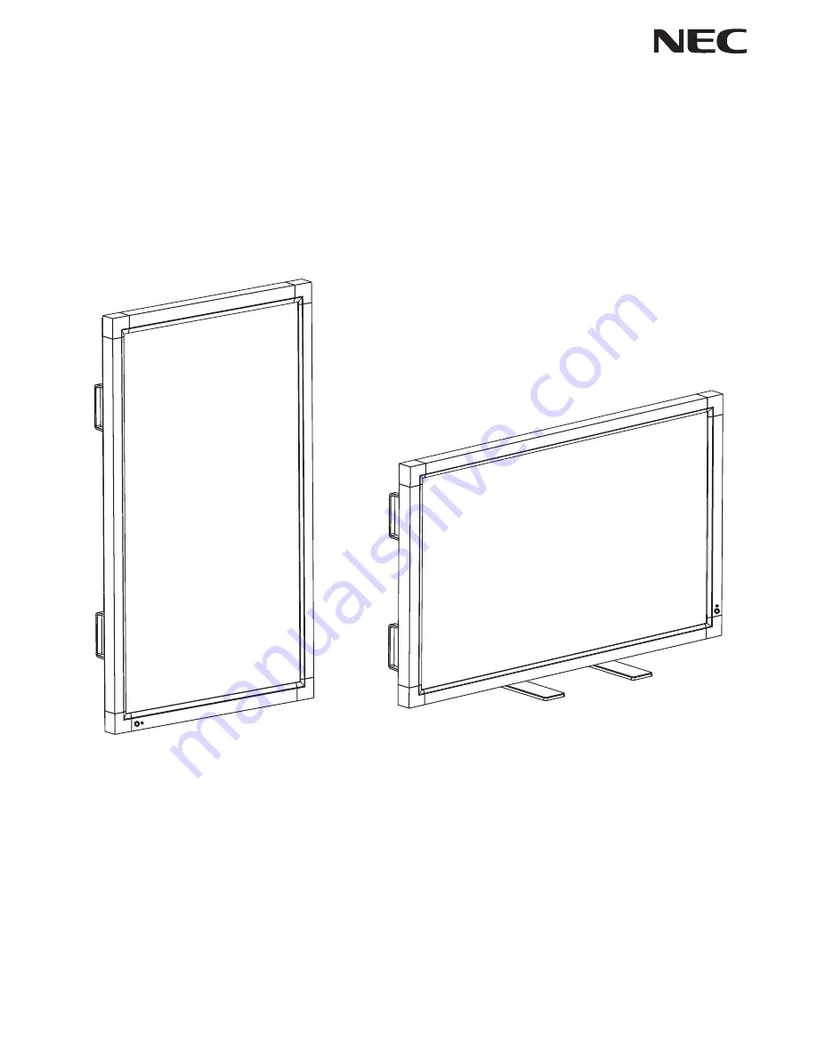
MultiSync LCD6520LMultiSync LCD6520P
(For use in Landscape position only)
(For use in Portrait position only)
Page 1: ...User s Manual MultiSync LCD6520L MultiSync LCD6520P For use in Landscape position only For use in Portrait position only ...
Page 2: ...ect the LCD Monitor to a DVD Player English 21 Connecting a DVD Player with HDMI out English 22 Connect the LCD Monitor to a DVD Player English 22 Connecting a DVD Player with SCART out English 22 Connect the LCD Monitor to a DVD Player English 22 Connecting to a Stereo Amplifier English 23 Connect the LCD Monitor to a Stereo Amplifier English 23 Basic Operation English 24 Power ON and OFF Modes E...
Page 3: ... required to correct the interference at his own expense If necessary the user should contact the dealer or an experienced radio television technician for additional suggestions The user may find the following booklet prepared by the Federal Communications Commission helpful How to Identify and Resolve Radio TV Interference Problems This booklet is available from the U S Government Printing Office...
Page 4: ... of the Manufacturer We hereby certify that the color monitor MultiSync LCD6520L L657TA MultiSync LCD6520P L657TB is in compliance with Council Directive 2006 95 EC EN 60950 1 Council Directive 2004 108 EC EN 55022 EN 61000 3 2 EN 61000 3 3 EN 55024 and marked with NEC Display Solutions Ltd 4 13 23 Shibaura Minato Ku Tokyo 108 0023 Japan CAUTION Please use the power cord provided with this display...
Page 5: ...t and dust at least once a year because of set reliability If using the cooling fan continuously it s recommended to wipe holes a minimum of once a month Immediately unplug your monitor from the wall outlet and refer servicing to qualified service personnel under the following conditions When the power supply cord or plug is damaged If liquid has been spilled or objects have fallen into the monito...
Page 6: ... Eyebolt x 2 Washer x 2 CD ROM Screw M4 x 10 x 4 Stand x 2 1 Type and number of power cords included will depend on the where the LCD monitor is to be shipped When more than one power cord is included please use a power cord that matches the AC voltage of the power outlet and has been approved by and complies with the safety standard of your particular country Install the stands at the time of unp...
Page 7: ...ure that it is strong enough to support the weight of the unit so that the unit will be safe from harm Refer to the instructions included with the mounting equipment for detailed information Installation LCD6520L Orientation DO NOT use this monitor in the portrait position Doing so may cause failure and void the warranty Unit Mounting Bracket Screw 15 mm Thickness of Bracket Screw length should eq...
Page 8: ... nothing on the table that can damage the monitor When using mounting accessories other than NEC compliant and approved they must comply with the VESA compatible mounting method NEC strongly recommends using screws M8 size and 15 mm in length If using screws longer than 15 mm check the depth of the hole Recommended Fasten Force 1125 1375N cm NEC recommends using a mounting interface that complies ...
Page 9: ... or chain to the monitor using the provided clamp and screw Before attaching the LCD monitor to the wall make sure that the wall can support the weight of the monitor Be sure to remove the cord or chain from the wall before moving the LCD 500mm 6 To prevent the main power switch from being used To attach main power switch cover Insert the tab on the switch cover into the slot on the display next t...
Page 10: ...CD ROM Eyebolt x 2 Washer x 2 CD ROM Screw M4 x 10 x 2 Washer x 2 Eyebolt x 2 User s Manual 1 Type and number of power cords included will depend on the where the LCD monitor is to be shipped When more than one power cord is included please use a power cord that matches the AC voltage of the power outlet and has been approved by and complies with the safety standard of your particular country Reme...
Page 11: ...e unit will be safe from harm Refer to the instructions included with the mounting equipment for detailed information Installation LCD6520P Orientation DO NOT use this monitor in the landscape position Doing so may cause failure and void the warranty LCD6520P can not rotate a displayed image from Landscape to Portrait Content must be created for use in portrait mode Unit Mounting Bracket Screw 15 ...
Page 12: ...ay is designed for use with the VESA mounting system When using mounting accessories other than NEC compliant and approved they must comply with the VESA compatible mounting method NEC strongly recommends using screws M8 size and 15 mm in length If using screws longer than 15 mm check the depth of the hole Recommended Fasten Force 1125 1375N cm NEC recommends using a mounting interface that compli...
Page 13: ...he tab on the switch cover into the slot on the display next to the main power switch Secure into place using 1 screw NOTE With the main power switch cover in place the main power switch cannot be turned off Remove main power switch cover in order to switch off the display See Parts Name and Functions on page 12 ...
Page 14: ...ks out access to all Control Key functions To activate the control key lock function press both and and hold down simultaneously for more than 3 seconds To resume user mode press both and and hold simultaneously for more than 3 seconds The product you purchased may not have this feature 1 POWER button Switches the power on off See also page 24 2 MUTE button Switches the audio mute ON OFF 3 INPUT b...
Page 15: ...5W 8 ohm speaker 13 RF IN For U S TV signal input 14 S PDIF OUTPUT For U S Optical digital audio out 15 Main Power Switch On Off switch to turn main power ON OFF The product you purchased may not have this feature 1 AC IN connector Connects with the supplied power cord 2 DVI IN DVI D To input digital RGB signals from a computer or HDTV device having a digital RGB output This connector does not sup...
Page 16: ...p menu See page 27 12 EXIT button Returns to previous menu within OSD menu 13 UP DOWN button Acts as button to move the highlighted area up or down to select adjustment items within OSD menu Small screen which adjusted PIP mode moves up or down 14 MINUS PLUS button Increases or decreases the adjustment level within OSD menu settings Small screen which adjusted PIP mode moves left or right 15 SET b...
Page 17: ...ong illumination strikes the remote control sensor of the LCD monitor or when there is an object in the path Handling the remote control Do not subject to strong shock Do not allow water or other liquid to splash the remote control If the remote control gets wet wipe it dry immediately Avoid exposure to heat and steam Other than to install the batteries do not open the remote control REMOTE ID but...
Page 18: ... to scratch the panel 2 Install the remote control batteries The remote control is powered by two 1 5V AA batteries To install or replace batteries NEC recommends the following battery use Place AA size batteries matching the and signs on each battery to the and signs of the battery compartment Do not mix battery brands Do not combine new and old batteries This can shorten battery life or cause li...
Page 19: ...he screen See pages 27 and 28 Make adjustments of the screen display position when necessary 9 Adjust the image See page 27 Make adjustments such as brightness or contrast when required 10 Recommended Adjustments To reduce the risk of the Image Persistence please adjust the following items based on the application being used SCREEN SAVER SIDE BORDER COLOR See page 30 DATE TIME SCHEDULE SETTINGS Se...
Page 20: ... Computer To connect the VGA IN connector mini D sub 15 pin on the LCD monitor use the supplied PC Video RGB signal cable mini D sub 15 pin to mini D sub 15 pin To connect the RGB HV connector BNC on the LCD monitor use a mini D sub 15 pin to BNC x 5 signal cable sold separately Select RGB HV from the INPUT button When connecting one or more LCD monitors use the RGB OUT connector BNC BNC INPUT onl...
Page 21: ...more information about your computer s video output requirements and any special identification or configuring your monitor s image and monitor may require AUDIO IN 1 2 and 3 can be used for audio input To select audio source IN1 IN2 or IN3 press the AUDIO INPUT button Connecting to a Macintosh Computer Connecting your Macintosh computer to your LCD monitor will enable you to display your computer...
Page 22: ... D cable Input TMDS signals conforming to DVI standards To maintain display quality use a cable that conforms to DVI standards AUDIO IN 1 2 and 3 can be used for audio input To select audio source IN1 IN2 or IN3 press the AUDIO INPUT button For mode selection see DVI MODE on page 31 Connecting with Digital Interface Equipment Connections can be made with equipment that is equipped with a digital i...
Page 23: ...enu For mode selection see DVI MODE on page 31 AUDIO IN 1 2 and 3 can be used for audio input To select audio source IN1 IN2 or IN3 press the AUDIO INPUT button Connecting a DVD Player with component out Connecting your DVD player to your LCD monitor will enable you to display DVD video Refer to your DVD player user s manual for more information LCD monitor To audio left output DVI D connector RCA...
Page 24: ...To connect the DVD HD IN connector RCA on the LCD monitor and connect the video sync and the Video In connector RCA use an RCA connector cable sold separately Some DVD players may have different connectors such as DVI D connector Select ON mode from the SCART MODE menu when you use a SCART connector For mode selection see SCART on page 31 The AUDIO IN 1 2 and 3 RCA can be used for audio input To s...
Page 25: ...amplifier Do not reverse the audio left and right jacks The AUDIO IN is used for audio input The AUDIO OUT jack outputs sound from the selected Audio input Connecting to a Stereo Amplifier You can connect your stereo amplifier to your LCD monitor Refer to your amplifier owner s manual for more information LCD monitor RCA To audio right output To audio left output To audio right input To audio left...
Page 26: ...ile powered on and will turn amber while powered off NOTE The Main Power Switch must be in the ON position in order to power up the monitor using the remote control or the Power Button on the front of the LCD Power Button Main Power Switch LCD6520L LCD6520P Power Button Main Power Switch ON OFF ON OFF ...
Page 27: ...hown ZOOM ZOOM 1 ID number assigned to current monitor 2 ID number assigned monitor to be controlled via RS 232C 3 Input Source 4 Audio input mode 5 Picture size 6 Input Signal Information 7 Sub picture information Using Power Management The LCD monitor follows the VESA approved DPM Power Management function The power management function is an energy saving function that automatically reduces the ...
Page 28: ... EXIT Remote Control Press UP or DOWN button to select Press INPUT button to decide Press UP or DOWN PLUS or MINUS button to select Press EXIT Control Panel OSD screen ADAPTIVE CONTRAST Goto Adjustment Select Return Close Input source Main Menu Icons Main Menu Item Sub Menu Key Guide Adjustment Settings NOTE Some functions may not be available depending on the model or optional equipment ...
Page 29: ... panel 2 2 Typical display gamma for use with a PC 2 4 Good for video TV DVD etc S GAMMA Special gamma for certain types of movies Raises the dark parts and lowers the light parts of the image S Curve DICOM SIM DICOM GSDF curve simulated for LCD type PROGRAMMABLE A programmable gamma curve can be loaded using NEC software ADAPTIVE CONTRAST Sets the level of adjustment for dynamic contrast HDMI DVD...
Page 30: ...zoom Can be adjusted for each BASE ZOOM setting H POS 2 Horizontal position Can be adjusted for each BASE ZOOM setting V POS 2 Vertical position Can be adjusted for each BASE ZOOM setting INPUT RESOLUTION If there is a problem with signal detection this function forces the monitor to display the VGA RGB HV inputs only signal at the desired resolution If no problem is detected the only available op...
Page 31: ...ESPAÑOL SVENSKA OSD TURN OFF Turns off the OSD after a period of inactivity The preset choices are 10 240 seconds OSD POSITION Determines the location where the OSD appears on the screen UP DOWN LEFT RIGHT INFORMATION OSD Selects whether the information OSD is displayed or not The information OSD will be displayed when the input signal or source changes The information OSD will also give a warning...
Page 32: ...tory setting MONITOR ID IR CONTROL TILE MATRIX POWER ON DELAY DISPLAY POWER SAVE Sets how long the monitor waits to go into power save mode after a lost signal PROTECTION All inputs except for TV Note When connecting DVI video card might not stop sending digital data even if image has disappeared In this case the monitor does not get to power management mode STANDBY MODE Lowers power consumption N...
Page 33: ...y RED DELAY Adjusts the phase of the red signal GREEN DELAY Adjusts the phase of the green signal BLUE DELAY Adjusts the phase of the blue signal RED SHARPNESS Adjusts the performance degradation of the RED signal GREEN SHARPNESS Adjusts the performance degradation of the GREEN signal BLUE SHARPNESS Adjusts the performance degradation of the BLUE signal SOG PEAK Adjusts the shape of Sync on Green ...
Page 34: ...he screen UNDER SCAN Image size stays within the display area The whole image is displayed on the screen ADVANCED OPTION Resets the following settings within the ADVANCED OPTION menu back to factory setting RESET INPUT DETECT LONG CABLE ON OFF LONG CABLE MANUAL DVI MODE SCAN CONVERSION S VIDEO MODE SCAN MODE FACTORY RESET Resets OSD options back to factory settings EXCEPT FOR CHANGE SECURITY PASSW...
Page 35: ...n the side of the monitor NOTE Cable distribution system should be grounded earthed in accordance with ANSI NFPA 70 the National Electric Code NEC in particular section 820 93 Grounding of Outer Conductive Shield of a Coaxial Cable 2 Enter the OSD and go to the TUNER menu below 3 In the TUNING BAND menu select which tuning method Air Cable Cable HRC Cable IRC will be used 4 Enter the CHANNEL SEARC...
Page 36: ...hemes indecent language graphic violence and explicit sexual content Video Parental Guide Ratings Chart OFF No Limitation G General audiences All ages are permitted to watch PG Parental guidance suggested Some material may not be suitable for children PG 13 Parents strongly cautioned Some material may be inappropriate for children under 13 R Restricted Under 17 requires an accompanying parent or a...
Page 37: ...permanent but constant images being displayed for a long period of time should be avoided To alleviate image persistence turn off the monitor for as long as the previous image was displayed For example if an image was on the monitor for one hour and a residual image remains the monitor should be turned off for one hour to erase the image As with all personal display devices NEC DISPLAY SOLUTIONS r...
Page 38: ...ng one PC or one infrared wireless controller up to 26 individual LCD6520L LCD6520P monitors can be controlled through a daisy chain via RS 232C connection 1 Connect PC and LCD6520L LCD6520P Connect a PC s RS 232C control output to the LCD6520L LCD6520P s RS 232C input You can then connect the RS 232C output from the LCD6520L LCD6520P to another LCD6520L LCD6520P s RS 232C input Up to 26 monitors ...
Page 39: ...n the CD included with the display The file is called External_control pdf When using the following control commands all of the daisy chained monitors can be controlled at the same time from one monitor Reply and status commands however will only pertain to the primary monitor not secondary monitors 1 Interface This LCD monitor uses RXD TXD and GND lines for RS 232C control 2 Control command diagr...
Page 40: ...onitor is powered on Command from computer Command from Monitor Detail of command 30 30 76 50 0D 0 0 v P enter Ask about the power status of monitor 30 30 76 50 31 0D 0 0 v P 1 enter Monitor is powered on Structure of the Read command Function Data Receive Function Data Receive ON vP 1 76 50 31 OFF stand by vP 0 76 50 30 DVI DVI D vI r1 76 49 72 31 VGA D SUB vI r2 76 49 72 32 RGB HV BNC vI r3 76 4...
Page 41: ...automatically optimizing display performance IPM Intelligent Power Manager System Provides innovative power saving methods that allow the monitor to shift to a lower power consumption level when on but not in use saving two thirds of your monitor energy costs reducing emissions and lowering the air conditioning costs of the workplace FullScan Capability Allows you to use the entire screen area in ...
Page 42: ...xt is garbled change the video mode to non interlace and use 60Hz refresh rate Image of component signal is greenish Check to see if the DVD HD input connector is selected LED on monitor is not lit no green or red color can be seen Power Switch should be in the ON position and power cord should be connected Make certain the computer is not in a power saving mode touch the keyboard or mouse RED LED...
Page 43: ... B H V Analog RGB Analog RGB Video 0 7 V p p with 75 ohm terminated Separate HV sync TTL level Posi Nega VIDEO BNC Composite Composite 1 0V p p with 75 ohm terminated AUDIO AUDIO RCA L R X2 Analog Audio Stereo L R 0 5 Vrms Input STEREO Mini Jack HDMI Type A Digital Audio PCM 32 44 1 48 KHz 16 20 24bit AUDIO STEREO Mini Jack Analog Audio STEREO Mini Jack L R 1 0 5 Vrms Output Speaker Output Externa...
Page 44: ...m NTSC 0 3 Vp p 75 ohm PAL SECAM NTSC PAL SECAM 4 43NTSC PAL60 Output Signal RGB HV BNC R G B H V Analog RGB Analog RGB Video 0 7 V p p with 75 ohm terminated Separate HV sync TTL level Posi Nega VIDEO BNC Composite Composite 1 0 V p p with 75 ohm terminated AUDIO AUDIO RCA L R X2 Analog Audio Stereo L R 0 5 Vrms Input STEREO Mini Jack HDMI Type A Digital Audio PCM 32 44 1 48 KHz 16 20 24bit AUDIO...
Page 45: ...DVI D DVI 4 RS 232C input output Pin No Name 1 connected to 7 8 2 RXD 3 TXD 4 connected to 6 5 GND 6 connected to 4 7 connected to 1 8 8 connected to 1 7 9 NC Pin Assignment of DVI connector 1 TX2 9 TX1 17 TX0 2 TX2 10 TX1 18 TX0 3 Shield TX2 TX4 11 Shield TX1 TX3 19 Shield TX0 TX5 4 NC 12 NC 20 NC 5 NC 13 NC 21 NC 6 DDC Serial Clock 14 5V power 22 Shield TXC 7 DDC Serial Data 15 Ground 23 TXC 8 N...
Page 46: ...cdisplay com in USA Energy Saving This monitor features an advanced energy saving capability When a VESA Display Power Management Signalling DPMS Standard signal is sent to the monitor the Energy Saving mode is activated The monitor enters a single Energy Saving mode Mode Power consumption LED color Normal Operation Approx 590W Green Energy Saving Mode Less than 7W Amber Mode Power consumption LED...