


English-9
English
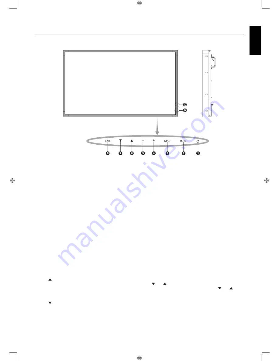
Control and Interface
(see attached display manual for details)
Control Panel
쐃
POWER button
Switches the power on/off.
쐇
MUTE button
Switches the audio mute ON/OFF.
쐋
INPUT button
Acts as SET button within OSD menu. (Toggle switches
between [DVI], [DPORT], [VGA], [RGB/HV], [HDMI],
[DVD/HD], [SCART], [VIDEO1], [VIDEO2] or [S-VIDEO]).
These are available input only, shown as their factory preset
name.
쐏
PLUS button
Acts as (+) button to increase the adjustment with OSD menu.
Increases the audio output level when the OSD menu is
turned off.
쐄
MINUS button
Acts as (-) button to decrease the adjustment with OSD menu.
Decreases the audio output level when the OSD menu is
turned off.
쐂
UP button
Activates the OSD menu when the OSD menu is turned-off.
Acts as button to move the highlighted area up to select
adjustment items within OSD menu.
쐆
DOWN button
Activates the OSD menu when the OSD menu is turned-off.
Acts as button to move the highlighted area down to select
adjustment items within OSD menu.
쐊
EXIT button
Activates the OSD menu when the OSD menu is turned-off.
Acts as EXIT button within the OSD to move to previous
menu.
쐎
Remote control sensor and Power Indicator
Receives the signal from the remote control (when using the
wireless remote control).
Glows green when the LCD monitor is in active mode*.
Glows red when the LCD is in POWER OFF mode.
Glows amber when the monitor is in Power Save Mode.
Green and Amber blink alternately while in Power Standby
mode with the “SCHEDULE SETTINGS” function enabled.
When a component failure is detected within the monitor, the
indicator will blink red.
* If “OFF” is selected in “POWER INDICATOR”, LED will not
light when the LCD monitor is in active mode.
쐅
AMBIENT LIGHT SENSOR
Detects the level of ambient light, allowing the monitor to
make automatic adjustments to the brightness setting,
resulting in a more comfortable viewing experience. Do not
cover this sensor.
Control Key Lock Mode
This control completely locks out access to all Control Key
functions. To activate the control key lock function, press
both and and hold down simultaneously for more than
3 seconds. To resume user mode, press both and and
hold simultaneously for more than 3 seconds.
01_English.indd 9
01_English.indd 9
2/17/12 8:36:09 AM
2/17/12 8:36:09 AM


