background image


- 3- 

1.2  Safety Instructions for Installation (Precautions) 

 
Notation  Used  in  this  Document 

The  following  symbols  are  used  in  this  document. 


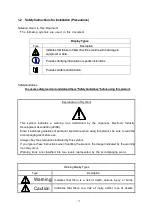
Display Types


Type


Description


Indicates that failure to follow directions could result in damage to 
equipment or data.


Provides clarifying information or specific instructions


Provides additional information.


Safety Guidelines


To ensure safety, read and understand these "Safety Guidelines" before using this product. 


Explanation of Symbol 


This  symbol  indicates  a  warning  icon  determined  by  the  Japanese  Electronic  Industry 
Development Association (JEIDA). 
Since it indicates guidelines of particular importance when using this product, be sure to read the 
accompanying text before use. 
Always obey the precautions indicated by this symbol. 
If you ignore these instructions when handling the product, the danger indicated by the warning 
icon may occur. 
Warning  icons  are  classified  into  two  levels  represented  by  the  accompanying  word. 


Warning Display Types   

Type 

Description 


Warning 

Indicates  that  there  is  a  risk  of  death,  serious  injury,  or  burns. 


Caution 

Indicates  that  there  is  a  risk  of  injury  and/or  loss  of  assets.


Summary of Contents for M100

Page 1: ... 856 857387 101 A 856 857387 101 A NEC Storage M100 M300 M500 M700 Disk Array Unit Installation Guide ...

Page 2: ...nstallation of the DiskArray Unit 13 5 1 Check the Floor Load 13 5 2 Means of Preventing Rack from Tipping Over 15 5 3 Rack Mounting Rules 15 5 4 Air Flow 16 5 5 Uninterruptible Power Supply UPS 18 6 Precautions 19 6 1 Precautions When Mounting DiskArray Units in an Unauthorized Rack 19 6 2 Directions for Safe Mounting 19 6 3 Precautions When Installing or Moving a DiskArray Unit 20 ...

Page 3: ...M700 disk array unit This installation guide presents guidelines that should be kept in mind during installation so that your NEC Storage series unit can be used properly After reading this guide store it carefully where you can quickly reference whenever necessary Tenth edition Nov 2013 ...

Page 4: ...l This symbol indicates a warning icon determined by the Japanese Electronic Industry Development Association JEIDA Since it indicates guidelines of particular importance when using this product be sure to read the accompanying text before use Always obey the precautions indicated by this symbol If you ignore these instructions when handling the product the danger indicated by the warning icon may...

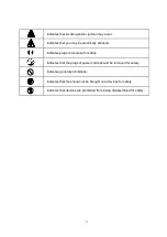
Page 5: ...lly shocked Indicates proper procedure for safety Indicates that the plugs of power cords should be removed for safety Indicates general prohibitions Indicates that fire should not be brought near devices for safety Indicates that devices are prohibited from being disassembled for safety ...

Page 6: ... more than 15 C per hour so that condensation does not occur Be sure to satisfy the following installation conditions when operating the disk array unit If the disk array unit is operated in an environment that does not satisfy these conditions it may cause the unit to breakdown or may significantly shorten its replacement period Temperature 5 C to 40 C recommended range Do not install the disk ar...

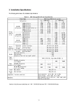
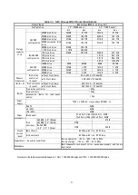
Page 7: ... 4TB SAS SSD configuration 100GB drive 89GB 897GB 89GB 897GB 200GB drive 187GB 1 4TB 187GB 1 4TB 400GB drive 387GB 3 7TB 387GB 3 7TB 800GB drive 757GB 5 9TB 757GB 5 9TB Chassis dimensions W D H Disk array controller U count without Front Bezel 482 513 2 87 8mm 2U with Front Bezel 482 545 2 87 8mm 2U Disk enclosure U count without Front Bezel 482 513 2 87 8mm 2U with Front Bezel 482 545 2 87 8mm 2U...

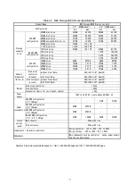
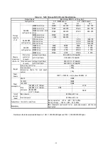
Page 8: ...B drive 187GB 1 4TB 187GB 1 4TB 400GB drive 387GB 3 7TB 387GB 3 7TB 800GB drive 757GB 5 9TB 757GB 5 9TB Chassis dimensions W D H Disk array controller U count without Front Bezel 482 513 2 87 8mm 2U with Front Bezel 482 545 2 87 8mm 2U Disk enclosure U count without Front Bezel 482 513 2 87 8mm 2U with Front Bezel 482 545 2 87 8mm 2U Weight Disk array controller 31kg Disk enclosure 29kg Accessorie...

Page 9: ...87GB 1 4TB 400GB drive 387GB 3 7TB 387GB 3 7TB 800GB drive 757GB 5 9TB 757GB 5 9TB Chassis dimensions W D H Disk array controller U count without Front Bezel 480 602 5 175 4mm 4U with Front Bezel 480 639 175 4mm 4U Disk enclosure U count without Front Bezel 482 513 2 87 8mm 2U with Front Bezel 482 545 2 87 8mm 2U Weight Disk array controller 39kg Disk enclosure 29kg Accessories Rails for rack moun...

Page 10: ...GB 1 4TB 187GB 1 4TB 400GB drive 387GB 3 7TB 387GB 3 7TB 800GB drive 757GB 5 9TB 757GB 5 9TB Chassis dimensions W D H Disk array controller U count without Front Bezel 480 602 5 175 4mm 4U with Front Bezel 480 639 175 4mm 4U Disk enclosure U count without Front Bezel 482 513 2 87 8mm 2U with Front Bezel 482 545 2 87 8mm 2U Weight Disk array controller 48kg Disk enclosure 29kg Accessories Rails for...

Page 11: ...sing SSD RAID 1 x 2 However at least three disk drives must be installed at the beginning of the main chassis in the disk array unit 2 Maximum capacity when using SAS NL SAS disk drive RAID 5 8 P When using SSD RAID 5 4 P 3 AC input power inlet corresponds to IEC320 C 14 ...

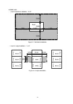
Page 12: ...form necessary maintenance of installed equipment At least 1 0 m in the front and rear of the rack At least 0 6 m to the left and right of the rack when racks are coupled to the left and right of the coupled unit At least 0 4 m from the top of the rack to the ceiling Figure 4 1 InstallationArea 1 0 m 0 6 m 0 4 m from top of rack to ceiling 0 6 m 1 0 m ...

Page 13: ...ea Figure 4 2 shows the required service area Aservice area of at least 1 0 m is required in the front and rear of the disk array unit Figure 4 2 ServiceArea Service area Service area Rack top view Front 1 0 m 1 0 m ...

Page 14: ...nits installed in the rack Also the weight that can be installed differs according to the rack that is used Discuss this with the operations or maintenance personnel in charge Sample calculation of the weight on the floor where the rack is located Assumed conditions M100 1DAC 7DE case Rack weight 170 kg Total weight of disk array units 31kg 3kg 29kg 3kg x 7 258kg Installation area when a standalon...

Page 15: ...alone Installation Area for coupled installation 1 2 m2 Figure 5 1 2 Coupled Installation 1 0 m 0 6 m 1 0 m 1 0 m 0 6 m 0 6 m Rack 0 6m 1 0 m 0 5 m 0 5 m Rack Front Rear Rack Front Rear Rack Front Rear Rack Front Rear Rack Front Rear Rack Front Rear Rack Front Rear Rack Front Rear ...

Page 16: ...s approximately 42 kg and M700 Disk array controller Accessory is approximately 51 kg If an appropriate method cannot be found to fasten the rack to the floor attach a stabilizer Someone might be injured if vibration caused the rack to tip over 5 3 Rack Mounting Rules To prevent the entire rack from becoming unstable when disk array units are mounted in the rack mount heavier units at the bottom a...

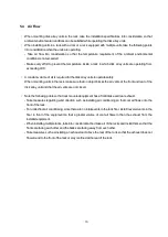
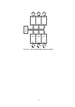
Page 17: ... no object blocks the air vents at the front and rear of the disk array unit and that the air vents are not closed Note the following points so that rack mounted equipment has a front intake and rear exhaust Take measures regarding wind direction such as installing air conditioning so that cool air flows onto the front of the rack For under floor air conditioning since there are no intake vents in...

Page 18: ... 17 Figure 5 4 Air Flow When Multiple Racks are installed Front Front Front Rear Front Rear Front Rear Front Air conditioning Rear Rear Rear ...

Page 19: ...t a UPS that permits this current The disk array unit is equipped with switching power supplies and an X Y capacitor to counter EMI at its input When numerous devices are connected to the UPS the leading phase current due to the capacitor increases Since a large oscillating current may occur in some UPS devices due to this leading phase current causing the circuit breaker between the UPS and disk ...

Page 20: ...mounting units in the rack make sure that no object blocks the air vents at the front and rear of the disk array unit and that the air vents are not closed Fasten the rack to the floor Use an appropriate method of fastening the rack to the floor so that mounting disk array units in the rack does not cause the entire rack to become unstable Be careful not to injure yourself when mounting disk array...

Page 21: ...humidity dust or oily smoke a poorly ventilated location or any location with fire This will cause the disk array unit to fail catch fire or cause an electric shock Do not use any other power cord than the one supplied with the disk array unit Using another power cord may cause a fire to occur Do not use the disk array unit with a voltage other than the one shown on the nameplate Also do not overl...

Page 22: ...exposed to direct sunlight Install the disk array unit in a location with little dust and low humidity Install the disk array unit in a flat stable location where severe vibrations do not occur Alocation subject to severe vibrations or an unstable location such as an inclined surface may cause the unit to fall or tip over Do not install the disk array unit near a passageway If it is installed near...

Page 23: ...nel cable is thin and easily damaged Do not excessively bend it or force it into the device Moving the disk array unit through an extremely uneven area may subject the device to shocks or vibrations and cause data loss Also pay careful attention to steps or gaps in the floor surface such as the gap at the entrance of an elevator At least two people should carry a disk array unit on a slope since t...

Page 24: ...orporation 5 7 1 Shiba Minato ku Tokyo Japan 81 3 3454 1111 NEC Corporation 2011 2013 No part of the content of this manual may be produced or transmitted in any form or by any means without the written permission of the NEC Corporation Information in this manual is subject to change without notice ...

Reviews: