CHAPTER 2 NAME AND FUNCTION OF COMPONENTS
20
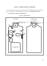
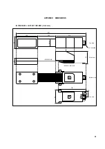
(1) Test pin (TP4-TP7)
These pins are used for testing analog signals for the emulator as a standalone unit.
•
TP4: AV
REF
•
TP5: AV
SS
•
TP6: AV
DD
•
TP7: P70 (Analog port)
(2) JP1
This is the switch jumper of the main clock supply source. (For details, refer to 2.2 Clock Settings)
(3) JP2
This is a pin block for supplying the subclock. (For details, refer to 2.2 Clock Settings)
(4) LED
LED for V
PP
ON: Voltage is applied to V
PP
OFF: Voltage is not applied to V
PP
(5) Connector for IE-703002-MC connection
This is a connector to connect with the IE-703002-MC.
(6) Connector for target connection
This is a connector to connect the target system or the extension probe.


