background image

E – 44

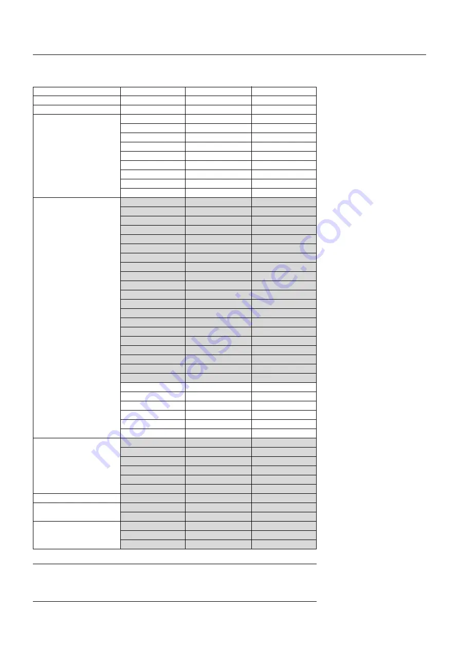
8. COMPATIBLE INPUT SIGNAL LIST

Compatible Input Signal List

NOTE 1:

The VGA, SVGA, XGA and UXGA signals are displayed with Advanced AccuBlend.

NOTE 2:

 UXGA can be supported for separate sync signal only.

NOTE 3:

 DVI digital signal can support a maximum resolution of SXGA@75Hz.

NOTE 4:

 Digital signals are indicated in shaded areas.

HIGHlite 4000Dsx requires the optional  DIGITAL RGB BOARD (DVI-D) to accept these digital signals.

640

768

640

1280

1920

1920

1920

1920

1920

1920

1920

640

640

720

640

640

640

640

800

800

800

800

800

1024

1024

1024

1024

1152

1280

1280

1280

1280

1600

1600

1600

1600

1600

640

832

1024

1152

1280

1280

1280

1152

1280

1024

1152

1280

480

576

480p

720p

1035

1080p

1080p

1080i

1080i

1080i

1080p

350

400

400

480

480

480

480

600

600

600

600

600

768

768

768

768

864

960

1024

1024

1024

1200

1200

1200

1200

1200

480

624

768

870

1024

1024

1024

900

1024

768

900

1024


Signal Name

Resolution (H

V)

Horizontal Frequency

Vertical Frequency

Video (NTSC)

Video (PAL/SECAM)

Video (HDTV)

IBM PC or Compatibles

Apple Macintosh

HP

SUN

SGI

15.734

15.625

31.5

45.0

33.75

28.13

33.72

28.13

33.75

26.97

26.97

31.5

37.9

37.0

31.5

37.9

37.5

43.3

35.2

37.9

48.1

46.9

53.7

48.4

56.5

60.0

68.7

67.5

60.0

64.3

80.0

91.1

75.0

81.3

87.5

93.8

106.3

34.9

49.7

60.2

68.7

64.3

74.9

78.1

61.8

81.1

49.7

71.7

63.9

60.0

50.0

60.0

60.0

60.0

25.0

30.0

50.0

60.0

47.95

23.98

70.0

85.0

85.0

60.0

72.8

75.0

85.0

56.3

60.3

72.0

75.0

85.0

60.0

70.1

75.0

85.0

75.0

60.0

60.0

75.0

85.0

60.0

65.0

70.0

75.0

85.0

66.6

74.6

74.9

75.6

60.4

69.9

72.0

66.0

76.0

60.4

76.1

60.0

Summary of Contents for HIGHlite 4000Dsx

Page 1: ...HIGHlite 4000Dsx HIGHlite 6000Dsx Super High Brightness Digital Video Projector User Manual ...

Page 2: ...idential area is likely to cause harmful interference in which case the user will be required to correct the interference at his own expense CAUTION RISK OF ELECTRIC SHOCK DO NOT OPEN RISQUE D ELECTROCUTION NE PAS OUVRIR ATTENTION CAUTION TO REDUCE THE RISK OF ELECTRIC SHOCK DO NOT OPEN COVER NO USER SERVICEABLE PARTS IN SIDE REFER SERVICING TO QUALIFIED SERVICE PERSONNEL This symbol warns the use...

Page 3: ...OWER indicator has not changed to a steady amber glow Immediately after the cooling fan stops working After the projec tor is turned off with the POWER OFF button the cooling fan con tinues to work for 3 minutes while the Two Digit INDICATOR flashes For North America For Europe Cleaning 1 Unplug the projector before cleaning 2 Clean the cabinet periodically with a damp cloth If heavily soiled use ...

Page 4: ...ns sur le Lamp Mode Mode Lampe AVERTISSEMENT Ne pas regarder dans l objectif lorsque le projecteur est allumé De sérieux dommages aux yeux pourraient en résulter Recommandations importantes Ces instructions de sécurité ont pour but d assurer une longue vie à votre projecteur et d éviter un incendie ou une décharge électrique Prière de les lire avec attention et de tenir compte de tous les avertiss...

Page 5: ... Methods of Immunity Characteristics of Information Technology Equipment EN 61000 3 2 1998 Harmonic Current Emissions EN 61000 3 3 1995 Immunity to Voltage Fluctuations and Flicker The technical documentation required to demonstrate that the products meet the requirements of the Low Voltage directive has been compiled by the signatory below and is available for inspection by the relevant enforceme...

Page 6: ...ABLE IN LINK MODE E 45 APPENDIX E 46 Dimensions E 46 Tips on Adjusting Focus for Lens Memory Function E 47 INTRODUCTION Introduction to the HIGHlite 6000Dsx 4000Dsx Projector E 1 Getting Started E 1 What s in the Box E 1 1 PART NAMES AND FUNCTIONS Projector E 2 Controls E 3 Terminal Panel E 4 Remote Control E 6 Remote Control Precautions E 7 Remote Control Battery Installation E 7 2 INSTALLATION S...

Page 7: ... the screen The remote control can be used in a wired or wireless configuration Features you ll enjoy A high performance 1 0 KW Xenon lamp that delivers 5000 ANSI lumens High Bright mode HIGHlite 6000Dsx 3 500 ANSI lumens Variable mode at max HIGHlite 4000Dsx with a lamp life of 1500 hours Digital Projection s unique DLPTM based light engine offers true color reproduction The HIGHlite 4000Dsx 6000...

Page 8: ...l will turn am ber in color Press to the OFF position 0 to turn the main power off NOTE When turning off the main power first return the projector to the standby condition by pressing the POWER OFF button on the remote control or the POWER button on the rear panel and then turn off the main POWER switch These pro cedures are necessary to protect your projector and the connected equipment Power Swi...

Page 9: ...nt projector ID address is shown in this two digit display In the event of an error a projector error code will be displayed The display can be turned off using the ON OFF Switch to the left hand side 5 Enter Button Executes your menu selection and activates items selected from the menu When the slidebar or dialog box is diplayed Pressing this button confirms adjustments setting and returns to the...

Page 10: ...r s IN terminal to relay the input at the IN terminal of the first projector until all the projectors are connected 5 INPUT 1 and INPUT 2 Terminals BNC Connect R G B H Horizontal sync and V Vertical sync outputs of the external equipment such as the Switcher If using a component with a combined sync SYNC output connect it to the H V terminal Also connect component video outputs Y Cb Cr of the exte...

Page 11: ...ptional SDI or SX HDSDI board Note SDILoopthroughonlyavailableonSDSDI 11 DVIDigitalVideoInterfaceRGBDigitalInput OutputConnectors Theseconnectorsareusedfordoubleortriplestacking Use the supplied DVI D 24 pin cable to connect the OUTPUT terminal of the first projector to the second projector s INPUT until all the projectors are connected DVI Standard on HIGHlite 6000Dsx option on 4000Dsx ...

Page 12: ...lly selects Pixel Adjust Position Aspect Ratio Resolu tion Overscan Video Filter Blanking While pressing and holding CTL pressing this button rotates On Off Timer Sleep Timer Menu Setup Link Mode Switcher Control 9 INPUT Use to select an input to name a signal or to enter a passcode during input registration 1 INPUT 1 for RGBHV Y Cb Pb Cr Pr 2 INPUT 2 for RGBHV Y Cb Pb Cr Pr 3 INPUT 3 for RGB 4 IN...

Page 13: ...to a shift key on a com puter Remote Control Precautions Use the remote control within a distance of about 7m 23feet and at an angle of 30 above below to the left and to the right of the remote control sensor located at the front of the main unit The remote control system may not function when direct sunlight or strong illumination strikes the remote control sensor of the main unit or when there i...

Page 14: ...43 8 34 3 1350 23 8 937 5 38 1 1500 TL 4Z 4 0 7 0 6 4 252 11 2 441 7 6 300 13 3 525 9 1 360 16 0 630 11 4 450 20 0 787 5 13 7 540 24 0 945 16 0 630 28 0 1102 5 18 3 720 32 0 1260 20 6 810 36 0 1417 5 22 9 900 40 0 1575 26 7 1050 46 7 1837 5 30 5 1200 53 3 2100 34 3 1350 60 0 2362 5 38 1 1500 66 7 2625 Screen Size 5 4 Screen size Diagonal Width H Height V TL 1Z 1ZH 1ZX 1ZHX H 1 5 H 2 5 TL 08SF H 0 ...

Page 15: ...H H width of projected image V height of projected image Desktop Front Vertical Normal position Max 0 41V 1V 0 19H 0 28H 0 41V 0 24V V H Normal Projection position Ceiling Front Vertical Normal position Max 0 41V 1V H V 0 41V 0 24V Normal Projection position 0 19H 0 28H Example for Stack Screen center Fixed Lens TL 08SF Maximum Possible Range for TL 08SF Up 0 09 V Right 0 06 H Down 0 09 V Left 0 0...

Page 16: ...everely dam aged Do not use the projector where temperatures vary greatly The pro jector must be used at temperatures between 40 degrees F 5 de gree C and 95 degrees F 35 degree C Do not expose the projector to moisture dust or smoke This will degrade the screen image Ensure that you have adequate ventilation around your projector for proper heat dissipation Do not cover the vents on the projector...

Page 17: ...he projector for three minutes This will extend the life of the lamp After the cooling fan stops working the POWER indicator will change to a steady orange glow and the projector will be in the stand by mode Then turn off the main power switch on the rear panel The POWER indicator will go out If you desire to move the projector then unplug the power cable NOTE Immediately after turning on the proj...

Page 18: ... ADJUST ABC DEF GHI JKL MNO PQR STU UNDO CANCEL TEST PICTURE KEYSTONE AMPLITUDE ENTRYLIST SOUND OSD MUTE MAGNIFY HELP INFO POSITION AUTO PIXEL VWX YZ WHITE BAL IMAGE ON POWER MENU ENTER 1 2 3 4 5 6 7 0 8 9 ADDRESS PROJECTOR R G B LENS SHUTTER BS FOCUS ZOOM CTL LENS MENU ENTER 2 Press the Enter button to execute the selection MENU ENTER 3 The Basic Custom menu will be displayed in the language you ...

Page 19: ... control or the LENS SHIFT button on the projector cabinet to move the image horizontally and vertically To close the the Lens Shift adjustment screen press the CANCEL button See page E 9 for Lens Shift Adjustable Range POSITION LENS CTL 2 Press and hold the CTL and press the ZOOM or button to adjust the image size You can also adjust the image size by using the ZOOM or button on the projector cab...

Page 20: ...l Data Preparation 3 1 Create data for the master projector and copy data to the slave projector 3 1 1 Choose one projector as the master 3 1 2 Turn the master projector on 3 1 3 Display all desired input signals make adjustment to each signal then save all adjustments on the master projector Ad justments will be saved automatically 3 1 4 Turn the master projector off standby mode 3 1 5 Store all ...

Page 21: ...elect Projector Options Setup Page 5 Communication Speed See page E 39 for setting the com munication speed 6 2 2 Select the appropriate speed between 4800 and 38400 6 3 Set the Link Mode on each projector 6 3 1 Select Projector Options Link Mode 6 3 2 First select Slave on the slave projector 6 3 3 Select Master on the master projectors See page E 39 for setting Link Mode 6 4 Project a source ima...

Page 22: ...ur projector on the ceiling must be done by a qualified technician Contact your Digital Projection dealer for more information Do not attempt to install the projector yourself Only use your projector on a solid level surface If the projector falls to the ground you can be injured and the projector severely dam aged Do not use the projector where temperatures vary greatly The pro jector must be use...

Page 23: ...a s video output requirements 4 CONNECTIONS INPUT3 RGB R Cr G Y B Cb H HV V R Cr Cr Y G Y B Cb Cb H HV V OPTION IN OUT REMOTE1 REMOTE2 INPUT7 INPUT8 INPUT5 S VIDEO1 Y C S VIDEO2 VIDEO1 VIDEO2 INPUT6 IN OUT INPUT2 INPUT1 INPUT4 PC control ISS 6020 Switcher Wired remote control PC Document camera DVD player PC Workstation DVD player VCR LD player Document camera ConnectingYourVCROrLaserDiscPlayer Us...

Page 24: ...terminal will not work with the Switcher Control function When connecting with the VIDEO INPUT MODULE 6020 VID set the VIDEO MODE select switch S3001 to 8 The VIDEO MODE select switch is located on the VIDEO INPUT MODULE 6020 VID NOTE While in the Switcher Control mode a video standard is selected at the projector If you set the VIDEO MODE select switch S3001 to 8 with the QUAD DECODER installed i...

Page 25: ...pment such as a personal computer RS 422 RS 232C for PC control of projector Set the DIP switch S8601 of the Switcher OPTION PC MASTER SWITCHER REMOTE CONTROL OPTION PC SLAVE 1 SLAVE 2 SLAVE 10 10 inputs 10 inputs 10 inputs Signal Switcher Signal REMOTE 1 REMOTE 2 Signal REMOTE 1 REMOTE 2 SLAVE 3 SLAVE 9 Signal REMOTE 1 REMOTE 2 REMOTE 2 To SLOT 1 To SLOT 2 To SLOT 10 To REMOTE 2 REMOTE 1 Signal I...

Page 26: ...1 Slave 2 Slave 3 Slave 4 Slave 5 Slave 6 Slave 7 Slave 8 Slave 9 Slave 10 ISS 6020 ISS 6020G Output to Setting of S8601 NOTE Slave numbers 1 to 10 must correspond to the master s slot numbers 1 to 10 OPEN SHORT 1 2 3 4 5 6 7 8 OPEN SHORT 1 2 3 4 5 6 7 8 OPEN SHORT 1 2 3 4 5 6 7 8 OPEN SHORT 1 2 3 4 5 6 7 8 OPEN SHORT 1 2 3 4 5 6 7 8 OPEN SHORT 1 2 3 4 5 6 7 8 OPEN SHORT 1 2 3 4 5 6 7 8 OPEN SHORT...

Page 27: ...Switcher or a third party external control device When the Switcher is used connect it with the optional control cable 15 15 pin 50 ft 16m CTL 6010 to this connector When using with the Switcher ISS 6020 ISS 6020G connect No 1 2 6 7 9 and15 pins of the projector to the same No pins of the switcher as shown below When used with the Switcher Pin No FUNCTION 1 2 6 and 7 Sending and receiving data whe...

Page 28: ... terminal The projector can be controlled by the same format signal as the supplied remote control from the external controller regardless of setting on Pin 14 NOTE When turning off the power to the projector using the external control do not disconnect the plug from the power outlet These procedures are to protect your projector and the connected equipment 11pin OPEN OPEN OPEN OPEN OPEN OPEN OPEN...

Page 29: ...ID 01 Projector ID 02 Projector ID 03 Remote Address 03 You can daisy chain multiple projectors and operate them separately with the same remote control in wired operation To do so 1 Use the remote control cable to connect the REMOTE 2 Output of one projector to the REMOTE 2 Input of the next projector until all the projectors are connected Only one remote control cable is supplied with each proje...

Page 30: ...s higher than SXGA 1280 X 1024 75Hz in Link mode Slave projector OUTPUT RGB DIGITAL INPUT9 OUTPUT RGB DIGITAL INPUT9 OUTPUT RGB DIGITAL INPUT9 OPTION IN OUT OPTION IN OUT OPTION IN OUT Master projector Slave projector Bi directional RS 232C cable not supplied Master projector Slave projector Slave projector Link Mode You can daisy chain up to 16 projectors and operate them separately with the same...

Page 31: ...ess the ADJUST PICTURE button or the ADJUST WHITE BAL on the remote control or select the Menu Adjust Source to adjust the picture 4 Turn Off The Projector First press the POWER OFF button on the remote control or the projector cabinet Allow the fan to cool the projector for three min utes This will extend the life of the lamp After the cooling fan stops working the POWER indicator will change to ...

Page 32: ...he changes use the or buttons to highlight Cancel and press the Enter button To return to the factory default select Reset then press the Enter button The default Basic Custom Menu items are Source Select RGB1 2 3 Component YCbCr Video1 2 S Video 1 2 DVI digital and SDI Brightness Contrast Pixel Adjust and Po sition NOTE Once you have selected OK on the Basic Custom Menu Edit screen you cannot can...

Page 33: ...s one letter or numeral in the entry screen CTL MUTE OSD Turns off the on screen display forcefully INPUT 1 10 in SW Level mode Displays the Select switcher Input Slot window NOTE This feature is available for SW 2 Level mode only When the SW 1 Level mode is selected pressing INPUT key switches to the corresponding slot without displaying the Select Slot window CTL MENU ADDRESS Displays the remote...

Page 34: ...n Overscan Video Filter Blanking Noise Reduction Color Matrix Y C Deray Telecine Motion Select Motion Level YTR Adjustment CTR Adjustment Clamp Timing Sync Protection VD Delay Gain Volume Reference Custom RGB Component Picture White Balance Image Video Adj Option Adj Lens Memory Signal Type Switcher Brightness R G B Contrast R G B Clock Phase Horizontal Vertical Input Signal 1 25 1 1 33 1 1 78 1 1...

Page 35: ...MM DD ddd Month DD YYYY Month DD YYYY ddd Date Time Preset On Off Timer Sleep Timer Timer Menu Setup Link Mode Switcher Control Execute Switch Active Inactive Edit Preset Time Off 0 30 1 00 1 30 2 00 Page 1 Page 2 Page 3 Page 4 Page 5 Orientation Desktop Front Ceiling Rear Desktop Rear Ceiling Front Background Blue Black Logo S Video Mode Select Off S2 Control Panel Key Lock Enable Disable Signal ...

Page 36: ...front Radio button Use this round button to select an option in a dialog box Check box Place a checkmark in the square box to turn the option On Slide bar Indicates settings or the direction of adjustment OK button Press to confirm your setting You will return to the previous menu Cancel button Press to cancel your setting You will return to the previous menu Help button Press the Help button on t...

Page 37: ...r Copy Enables you to copy a selected signal from the list and place it on the clipboard in the projector Paste Enables you to paste the signal placed on the clipboard to any other line of the list To do this select Paste and then select the line number you want to paste to Last press ENTER Edit Enables you to change source name or assign the direct key The following buttons are not available for ...

Page 38: ...when part of your image appears to be shimmering Use the 䊴 and 䊳 buttons to adjust the image Use Phase only after the Clock is complete NOTE When Auto Adjust is turned ON on the Page 4 of Setup the Clock adjust is not available on this Pixel Adjust screen Brightness Adjusts the brightness level or the back ras ter intensity Contrast Adjusts the intensity of the image according to the incoming sign...

Page 39: ...the image is displayed full screen using the Advanced AccuBlend feature NOTE The image with lower resolution than SXGA 1280 x 1024 is dis played in small when you are in the Native In this case you can use the lens shift zoom and focus adjustments which you saved in advance with Cus tom of Lens Memory to enlarge the image to fit on the screen Overscan You can select overscan percentage for RGB sig...

Page 40: ...nput signal Normally this is not used 1080P is set as the default Auto This is the normal setting Tri Sync This is set when projecting HDTV video Front Porch This is set when the picture quality does not improve even though Auto or Tri Sync has been set Adjust This permits the video clamp position for each signal to be set Use Adjust when a clamp timing error occurs at the time of special analog s...

Page 41: ...apsect ratio signals and 5 4 aspect ratio signals can now be displayed Note that with these shift focus and zoom adjustments the 4 3 aspect ratio signal will become smaller on the screen To eliminate this size reduction adjust the shift focus and zoom to the optimum condition for each of the 4 3 aspect ratio signal and the 5 4 aspect ratio signal Memory storage of each of these values will per mit...

Page 42: ...mer make sure that Date Time Preset feature is set Even after setting On Off Timer turning the projector on or off with the remote control is possible There are two time display formats 24 hour or AM PM format 1 Open the On Off Timer window 2 Select EDIT and press ENTER on the remote control to open the EDIT window 3 Set the Week Day On Time and Off Time using the Select buttons and Source buttons...

Page 43: ...ish German French Italian Spanish Swedish and Japanese Menu Display Time This option allows you to select how long the projector waits after the last touch of a button to turn off the menu The preset choices are Manual Auto 5 sec Auto 10 sec and Auto 30 sec The Manual is the factory preset Manual The menu can be turned off manually Auto 5 sec The menu will automatically be turned off in 5 seconds ...

Page 44: ...rmal use Select the Hi Z when inputting a TTL signal Page 3 Signal Select VIDEO 1 2 S VIDEO1 2 and Switcher This feature enables you to select composite video standards manu ally Normally select Auto Select the video standard from the pull down menu This must be done for Video and S Video separately Switcher is setting for Video and S Video in SW 1 Level or 2 mode Page 4 AutoAdjust RGBOnly When Au...

Page 45: ...he Link mode the Lens Memory feature is not available User Name Type in your desired name using the INPUT buttons on the remote control Select one character at a time with the INPUT buttons 1 through 10 0 and by moving the cursor with the SELECT button The user name must be 18 characters or less Only after completely finishing the selection of the characters press ENTER Page 5 CommunicationSpeed T...

Page 46: ...nals listed in the Entry List In this case the Auto Adjust feature may not work correctly To use both signals use different input terminal RGB 1 RGB 2 or RGB 3 respectively or assign specific remote keys for signals 1 Cut an existing signal from the Entry List 1 Select another signal other than the one currently projected because the currently projected signal cannot be cut 2 Press the ENTRY LIST ...

Page 47: ...l 15 107 kHz Vertical 24 105 Hz Pixel Clock 200MHz MAX Inputs RGB YCr Pr Cb Pb 2 BNC RGB H HV V 1 D dub 15 pin YPbPr YCrCb 1 RCA Video 1 BNC 1 RCA S Video 1 S Video Terminal Y C 1 BNC Digital I O Option on HIGHlite 4000Dsx RGB DIGITAL 1 DVI D 24pin type TMDS specification Max resolution SXGA 75Hz 1 Process Out DVI D 24pin type SDI Option1 1 BNC 1 BNC Through out SMPTE 259M Level C 4 2 2 525 625 Co...

Page 48: ...age 14 to 122 F 10 to 50 C Regulations USA UL 1950 FCC Class A Canada CSA950 C UL Europe EN60950 EN55022 Class A EN55024 EN61000 3 2 EN61000 3 3 Japan J60950 VCCI Oceania EN60950 AS NZS3548 Class A Asia EN60950 CISPR22 Class A 1 HIGHlite 6000Dsx Permissible deviation for RGB convergence Pixel deviation is 3 4 pixel or less at center 1 pixel or less around the perimeter when projection upward angle...

Page 49: ...or cable 1 and installation manual 1 HD SDI Board This board accepts the input of non compressed signal sources such as commercial type digital VCR D5 VCR compatible with digital serial component signals of the SMPTE 292M standard and provides a high quality image without quantization noise This board accepts the following image formats System 1920x1035 60 2 1 1920x1080 60 2 1 1280x720 60 1 1 1920...

Page 50: ...20p 1035 1080p 1080p 1080i 1080i 1080i 1080p 350 400 400 480 480 480 480 600 600 600 600 600 768 768 768 768 864 960 1024 1024 1024 1200 1200 1200 1200 1200 480 624 768 870 1024 1024 1024 900 1024 768 900 1024 Signal Name Resolution H V Horizontal Frequency Vertical Frequency Video NTSC Video PAL SECAM Video HDTV IBM PC or Compatibles Apple Macintosh HP SUN SGI 15 734 15 625 31 5 45 0 33 75 28 13 ...

Page 51: ...jector Slave projector s L valid linked N invalid invalid M valid invalid I independently adjustable independently adjustable See the table below for available functions in the digital link mode and the analog link mode See the table below for available functions in the digital link mode HIGHlite 6000Dsx only and the analog link mode The digital signals available in the Link mode are the VESA comp...

Page 52: ...E 46 506 19 92 326 12 83 174 6 85 682 26 85 35 5 1 40 300 11 81 30 1 18 70 2 76 The drawings do not include the lens part Unit mm inch APPENDIX Dimensions ...

Page 53: ...t data Preparation Recommend Warm up the projector for about 60 minutes Adjusting the Focus 1 Practice focusing Use the FOCUS or button on the projector or the remote control to increase the focus values or decrease the focus values to verify the accuracy of focusing 2 Try optimizing defocus Use the FOCUS button to decrease the focus values until pixel patterns are too blurry to be visible 3 Obtai...

Reviews: