background image


Disassembly and Reassembly - 4 

Fig. 3:  

Removing the front panel 


Note   

Be careful not to damage the switches and LEDs board 

when pulling. 

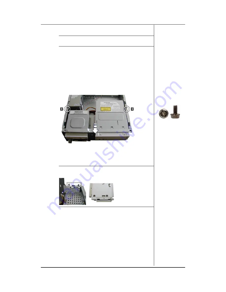
Removing the 3.5" / 5.25" Bay Assembly 

To remove the 3.5" and 5.25" bay assembly first open the 
chassis (see Opening the Chassis), then remove the front 
panel (see Removing the Front Panel) and follow the next 
steps: 

1.  Disconnect all data cable and power cable from the 

peripherals in the bays. 

2.  Remove the screws as shown. 


Fig. 4:  

Removing the 3.5" / 5.25" Bays 


3.  Slide the bays assembly towards the front of the chassis 

and then lift it away carefully. 


Note   

Slide the 3.5/5.25-inch bracket inside the chassis taking 

care that the four tabs of the chassis (two each side) fit in the four 
openings of the bracket 


Removing the FDD 

To remove the FDD, first open the chassis (see Opening the 
Chassis), then remove the front panel (see Removing the 
Front Panel) and remove the 3.5" / 5.25" bay assembly (see 
Removing the 3.5" / 5.25" Bay Assembly). After that, follow 
the next steps: 

1.  Remove the screws on the bottom of the FDD. 
2.  Slide out the FDD from the front of the bay. 


Summary of Contents for FlexATX Chassis

Page 1: ...FlexATX Chassis Disassembly Manual ...

Page 2: ...en disassembling the system unit follow these general rules n Do not disassemble the system into parts that are smaller than those specified in the instructions n Label all removed connectors Note where the connector goes and in what position it was installed n Turn off the power and disconnect all power and all options Electrostatic discharge can damage computer components Discharge static electr...

Page 3: ...ift it away Fig 2 Sliding away the cover Removing the Front Panel To remove the front panel first open the chassis see Opening the Chassis then do as follows 1 Press upwards on the three latches shown in Fig 3 to free them 2 Gently pull the right side of the front panel toward you in order to free two more latches found below the 5 25 bay 3 Once the right side is free pivot the front panel toward ...

Page 4: ...ws as shown Fig 4 Removing the 3 5 5 25 Bays 3 Slide the bays assembly towards the front of the chassis and then lift it away carefully Note Slide the 3 5 5 25 inch bracket inside the chassis taking care that the four tabs of the chassis two each side fit in the four openings of the bracket Removing the FDD To remove the FDD first open the chassis see Opening the Chassis then remove the front pane...

Page 5: ...ter that follow the next steps 1 Remove the screws on the bottom of the CD DVD ROM drive 2 Slide out the CD DVD ROM drive from the front of the bay Fig 6 Removing the CD DVD ROM drive from its bay Removing the HDD To remove the HDD first open the chassis see Opening the Chassis and then remove the 3 5 5 25 bay assembly see Removing the 3 5 5 25 Bay Assembly After that follow the next steps 1 Disco...

Page 6: ...screws that hold the hard disk drive to its bay Fig 9 Hard disk drive screws Removing the front USB panel To remove the front USB panel first open the chassis see Opening the Chassis remove the front panel see Removing the Front Panel and perform the next steps 1 Disconnect the USB cable and the LEDs cable from the motherboard 2 Remove the screws holding the USB panel in place Fig 10 Removing the ...

Page 7: ...g 11 Power supply screws 3 Slide the power supply away from the edges of the chassis and carefully lift it out of the system Removing the Intrusion Switch To remove the intrusion switch first open the chassis see Opening the Chassis then do as follows 1 Disconnect the cable of the intrusion switch from the motherboard 2 Pull the latches that hold the housing of the intrusion switch to the chassis ...

Page 8: ...remove the motherboard first open the chassis see Opening the Chassis then remove the 3 5 5 25 bay assembly see Removing the 3 5 5 25 Bay Assembly Remove any add on card see Removing Add On Cards When this is done perform the next operations 1 Disconnect all cables from the motherboard 2 Remove the memory modules and the CPU from the motherboard 3 Remove the screws that hold the motherboard in its...

Reviews: