background image

Appendix

Español

Français

Deutsch

English

Italiano

Controls

E - 15

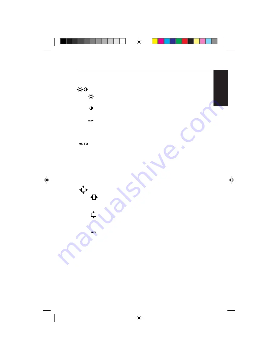
         Brightness/Contrast Controls

BRIGHTNESS
Adjusts the overall image and background screen brightness.

CONTRAST
Adjusts the image brightness in relation to the background.

AUTO ADJUST CONTRAST
Adjusts the image displayed for non-standard video inputs.

         Auto Adjust

Automatically adjusts the Image Position, H. Size and Fine
settings.

NOTE: Manual adjustment of the H/V Position and Image Adjust
H. Size / Fine controls may be required to complete setup of
your MultiSync monitor.

         Position Controls

H. POSITION
Controls Horizontal Image Position within the display area
of the LCD.

V. POSITION
Controls Vertical Image Position within the display area of
the LCD.

AUTO
Automatically sets the Horizontal and Vertical Image
Position within the display area of the LCD.

78134811.PM5

99.12.24, 2:19 PM

25

Summary of Contents for colour monitor

Page 1: ...truer representation of colour The monitor s high contrast LCD enhances colour vibrancy and improves focus with no geometric distortion Wider Compatibility Because the MultiSync LCD monitor is analog through and through it does not require special analog to digital display or interface cards but can accept RGB input directly Reduced Footprint Provides the ideal solution for environments requiring ...

Page 2: ...iew a full page on one screen at one time The Portrait orientation is also perfect for full screen video conferencing Plug and Play The Microsoft solution with the Windows operating system facilitates setup and installation by allowing the monitor to send its capabilities such as screen size and resolutions supported directly to your computer automatically optimizing display performance IPM Intell...

Page 3: ... to connect their MultiSync monitor to any VESA standard third party mounting arm or bracket Allows for the monitor to be mounted on a wall or an arm using any third party compliant device BNC D SUB Offers dual inputs allowing you to connect the monitor to one system via a BNC cable and a another system via a standard D Sub cable You can easily switch between computers with a touch of a button on ...

Page 4: ...2110 Model LA 2141JMW P AC power cable AC Adapter Type A2440S01 Video Signal Cable 15 pin VGA to BNC User s manual NEC LCD Setup Software Pivot Software and other helpful files Remember to save the original box and packing materials to transport or ship the monitor MultiSync LCD2110 monitor with 15 pin VGA to BNC Cable and AC Adapter BNC Cable 78134811 PM5 99 12 24 2 19 PM 14 ...

Page 5: ... they may touch dangerous voltage points which can be harmful or fatal or may cause electric shock fire or equipment failure Do not place any heavy objects on the power cord Damage to the cord may cause shock or fire Donotplacethisproductonaslopingorunstablecart standortable as the monitor may fall causing serious damage to the monitor Use the monitor in a clean and dry area Handle with care when ...

Page 6: ...Please note that OptiShield glass is not safety glass and is not laminated As with other glass OptiShield glass may break into sharp pieces if abused dropped or otherwise subjected to a substantial shock If OptiShield does break please use care to avoid injury MultiSync brand monitors equipped with OptiShield glass will have a reflective surface which under normal lighting conditions can cause eye...

Page 7: ...ightly below eye level Your eyes should look slightly downward when viewing the middle of the screen Position your monitor no closer than 40 cm and no further away than 70 cm from your eyes The optimal distance of MultiSync LCD2110 is 61 cm Rest your eyes periodically by focusing on an object at least 6 m away Position the monitor at a 90 angle to windows and other light sources to minimize glare ...

Page 8: ...nect the 15 pin mini D SUB of the appropriate signal cable to the connector of the display card in your computer Figure A 1 Figure B 1 Tighten all screws NOTE Some Macintosh systems require a Macintosh cable adapter 3 Remove connector cover on back of monitor Connect the BNC cables and AC adapter cable to the appropriate connectors on the back of the monitor Ifyouareusingthesuppliedvideosignalcabl...

Page 9: ...cable to D SUB connector on the back of the monitor Figure C 2 6 Replace connector cover NOTE Incorrect cable connections may result in irregular operation damage display quality components of LCD module and or shorten the module s life 7 Connect one end of the power cord to the AC Adapter and the other end to the power outlet Figure E 1 8 Turn on the monitor Figure F 1 and the computer 78134811 P...

Page 10: ...djust H Size Fine controls may be required to complete setup of your MultiSync monitor For a full description of these OSM controls refer to the Controls section of this User s Manual 10 Refer to User s Manual in the NEC LCD Setup Software CD case for installation and operation of this software NOTE If you have any problems please refer to the Troubleshooting section of this User s Manual E 10 Ins...

Page 11: ...k or pinching your fingers To raise the screen place hands on each side of the monitor and lift up to the highest position Figure RL 1 To rotate screen place hands on each side of the monitor screen and turn clockwise from Landscape to Portrait or counter clockwise from Portrait to Landscape Figure R 1 To toggle the orientation of the OSM menu between Landscape and Portrait modes press the RESET b...

Page 12: ...sch English Italiano E 12 Installation Tilt and Swivel Grasp both sides of the monitor screen with your hands and adjust the tilt and swivel as desired Figure TS 1 Figure R 1 Figure RL 1 Figure TS 1 78134811 PM5 99 12 24 2 19 PM 22 ...

Page 13: ...e stand is parallel with the surface Figure S 1 4 Press the portion with your index finger and at the same time slide the lower stand cover Figure S 2 Next lift up the stand remove the lower stand cover then go on to remove the upper stand cover Figure S 3 Return the stand to its original position remove the 4 screws that connect the monitor to the stand and lift off the stand assembly Figure S 4 ...

Page 14: ...ols Exits to the OSM main menu CONTROL Moves the highlighted Moves the highlighted area up down to select area up down to select one of the controls one of the controls CONTROL Moves the highlighted area Moves the bar left left rights to select right to increase or control menus decrease the adjustment PROCEED Has no function Activates Auto Adjust and ALL RESET functions RESET Resets the highlight...

Page 15: ...Adjust Automatically adjusts the Image Position H Size and Fine settings NOTE ManualadjustmentoftheH VPositionandImageAdjust H Size Fine controls may be required to complete setup of your MultiSync monitor Position Controls H POSITION Controls Horizontal Image Position within the display area of the LCD V POSITION Controls Vertical Image Position within the display area of the LCD AUTO Automatical...

Page 16: ...will appear on screen and the direction increase or decrease will be shown by the bars Tools OSM H POS OSM V POS You can choose where you would like the OSM control window to appear on your screen Selecting OSM Location allows you to manually adjust the position of the OSM control menu left right up or down ALL RESET Selecting ALL RESET when BNC input is selected allows you to reset all OSM contro...

Page 17: ...access to all OSM control functions When attempting to activate OSM controls while in the LOCK OUT mode a screen will appear indicating that OSM controls are locked out To enter the LOCK OUT mode simultaneously press the PROCEED and button The LOCK OUT window will appear To activate the LOCK OUT function simultaneously press and hold down the PROCEED and button The OSM window will disappear within...

Page 18: ...p p Display Colours Analog Input Unlimited number of colours Depends on the graphics board Synchronisation Horizontal 24 0 kHz to 82 0 kHz Automatically Range Vertical 56 0 Hz to 76 0 Hz Automatically Resolutions Landscape 720 x 400 VGA text Supported 640 x 480 at 60 Hz to 76 Hz 800 x 600 at 56 Hz to 76 Hz 832 x 624 at 75 Hz 1024 x 768 at 60 Hz to 76 Hz 1280 x 960 at 60 Hz to 76 Hz 1280 x 1024 at ...

Page 19: ...t are lower than the pixel count of the LCD module text may appear choppy or lines may appear to be bold This is normal and necessary for all current flat panel technologies each dot on the screen is actually one pixel so to expand resolutions to full screen an interpolation of the resolution must be done When the interpolated resolutions is not an exact multiple of the native resolution the mathe...

Page 20: ...ns Check that the BNC D SUB button is in the correct position Power Button does Unplug the power cord of the monitor from the AC not respond outlet toturnoffandresetthe monitor orsimultaneously press the RESET and Power buttons Image persistence Image persistence is when a ghost of an image remains on the screen even after the monitor has been turned off Unlike CRT monitors LCD monitors image pers...

Page 21: ...nge the video mode to non interlace and use 60Hz refresh rate LED on monitor is Power Switch should be in the ON position and power not lit no green or cord should be connected amber colour can be Make certain the computer is not in a power saving seen mode touch the keyboard or mouse Display image has a Select TYPE in the OSM Information menu and green cast to it press the or Control button Displ...

Reviews: