background image

English-4

6. No-touch Auto Adjust automatically  adjusts the monitor to optimal settings upon initial setup for most timings.

For further adjustments, use the following OSM controls:

• Auto Adjust Contrast

• Auto Adjust

Refer to the 

Controls 

section of this User’s Manual for a full description of these OSM controls.

NOTE:

If you have any problem, please refer to the 

Troubleshooting

 section of this

User’s Manual.

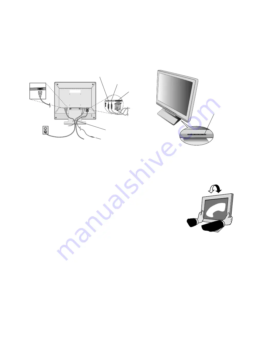
Tilt

Grasp both sides of the monitor screen with your hands and adjust the tilt as desired
(

Figure TS.1

).

Remove Monitor Stand for Mounting

To prepare the monitor for alternate mounting purposes:

1. Disconnect all cables.

2. Place monitor face down on a non-abrasive surface (

Figure R.1

).

3. Remove the 2 screws connecting the monitor to the stand and lift off the stand (

Figure R.1

)

4. Remove the 4 screws connecting the monitor to the stand and lift off the stand, assembly (

Figure R.2

).

The monitor is now ready for mounting in an alternate manner.

5. Connect the AC cord and signal cable to the back of the monitor (

Figure R.3

).

6. Reverse this process to reattach stand.

NOTE:

Use only VESA-compatible alternative mounting method.

NOTE:

Handle with care when removing monitor stand.

3. Connect the 15-pin mini D-SUB of the video signal cable, Audio Cable and Headphone (not included) to the appropriate

connector on the back of the monitor (

Figure B.1

).

4. Connect one end of the power cord to the monitor and the other end to the power outlet. Place the Video Signal Cable,

Headphone (not included) and power cord to the Cable holder (

Figure B.1

).

NOTE:

Adjust position of cable that place under the Cable holder to avoid damage for cable or monitor.

NOTE:

If you use this monitor at AC125-240V, please refer to Recommended Use section of this manual for proper
selection of power cord.

5. Turn on the monitor with the front power button and the computer (

Figure C.1

).

Figure TS.1

Figure B.1

HEAD PHONE

Cable holder

AUDIO INPUT

Input (D-Sub)

Connect to
Computer audio output

Figure C.1

Power Button

Summary of Contents for AccuSync LCD71VM

Page 1: ...AccuSync LCD51VM AccuSync LCD71VM User s Manual...

Page 2: ...a registred trademark of NEC Mitsubishi Electric Visual Systems Corporation in Austria Benelux Denmark France Germany Italy Norway Spain Sweden U K IBM PC XT AT PS 2 MCGA VGA 8514 A and XGA are regis...

Page 3: ...dio communications However there is no guarantee that interference will not occur in a particular installation If this equipment does cause harmful interference to radio or television reception which...

Page 4: ...Figure A 1 To attach the AccuSync LCD monitor to your system follow these instructions 1 Turn off the power to your computer 2 For the PC with Analog output Connect the 15 pin mini D SUB signal cable...

Page 5: ...he monitor is now ready for mounting in an alternate manner 5 Connect the AC cord and signal cable to the back of the monitor Figure R 3 6 Reverse this process to reattach stand NOTE Use only VESA com...

Page 6: ...th a flexible arm Please use the attached screws 4pcs as show in the picture when installing To meet the safety requirements the monitor must be mounted to an arm which guaranties the necessary stabil...

Page 7: ...st operate At OSD showing Icon selection stage Go to Adjustment stage Cursor goes to left Cursor goes to right At OSD showing Adjustment stage Go to Icon selection stage Adjust value decrease or Curso...

Page 8: ...lect the desired color setting COLOUR RED Increase or decreases Red The change will appear on screen COLOUR GREEN Increase or decreases Green The change will appear on screen COLOUR BLUE Increase or d...

Page 9: ...and serial numbers of your monitor OSM Warning OSM Warning menus disappear with Exit button NO SIGNAL This function gives a warning when there is no signal present After power is turned on or when the...

Page 10: ...ly unplug your monitor from the wall outlet and refer servicing to qualified service personnel under the following conditions When the power supply cord or plug is damaged If liquid has been spilled o...

Page 11: ...ard for you to see your screen use an antiglare filter Clean the LCD monitor surface with a lint free non abrasive cloth Avoid using any cleaning solution or glass cleaner Adjust the monitor s brightn...

Page 12: ...EC Mitsubishi Electronics Display cites 832 x 624 1 75 Hz recommended resolution at 75 Hz for 1024 x 768 60 Hz to 75 Hz optimal display performance Active Display Area Horizontal 304 1 mm Vertical 228...

Page 13: ...864 1 70 Hz to 75 Hz 1152 x 870 1 75 Hz NEC Mitsubishi Electronics Display cites 1280 x 960 1 60 Hz to 75 Hz recommended resolution at 75 Hz for 1280 x 1024 60 Hz to 75 Hz optimal display performance...

Page 14: ...pliance with MPRII and TCO guidelines for lower emissions Plug and Play The Microsoft solution with the Windows 95 98 Me 2000 XP operating system facilitates setup and installation by allowing the mon...

Page 15: ...image NOTE As with all personal display devices NEC Mitsubishi Electronics Displays recommends using a screen saver at regular intervals whenever the screen is idle or turning off the monitor when not...

Page 16: ...rict environmental demands for example in respect of the reduction of electric and magnetic fields physical and visual ergonomics and good usability Environmental Requirements Flame retardants Flame r...

Reviews: