background image

English

English-5

Screw Holes

Clamper

Cord or Chain

Screw

To avoid falling down

Fasten the LCD monitor to a wall using a cord or chain which is
sufficient to support the weight of the LCD monitor (approx. 28kg).

Before moving the LCD monitor, the cord or chain should be re-
moved.

Table

Protective Sheet

Tabletop Stand

You can attach mounting accessories to the LCD monitor in one of
the following two ways:

1.  In the upright position

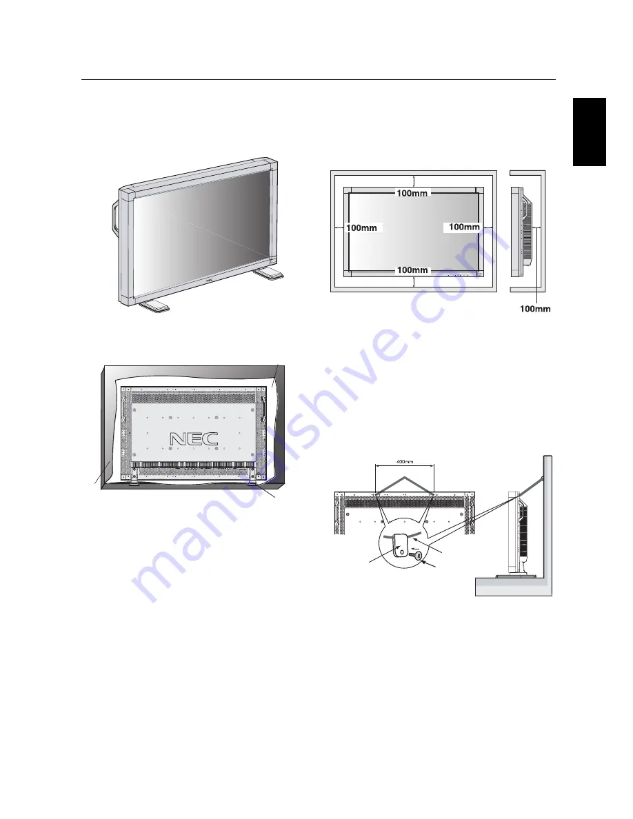
Ventilation Requirements for enclosure

mounting

To allow heat to disperse, leave space between surrounding
objects as shown in the diagram to the right.

Attaching LCD Options

2.  Lay the screen face down

To avoid damaging the screen face, place the protective sheet on
the table to lay the LCD on.  The protective sheet was wrapped
around the LCD in the original packaging.

This device cannot be used or installed without the Tabletop Stand
or other mounting accessory.  For proper installation it is strongly
recommended to use a trained, NEC authorized service person.
Failure to follow NEC standard mounting procedures could result in
damage to the equipment or injury to the user or installer. Product
warranty does not cover damage caused by improper installation.
Failure to follow these recommendations could result in voiding your
warranty.

When using mounting accessories, other than NEC compliant and
approved, they must be VESA

®

-compatible mounting method.   NEC

strongly recommends using screws M6 size and 8mm in length.  If
using screws longer than 8mm, check the depth of the hole.
(Recommended Fastern Force: 274 ~ 362N

cm)

NEC recommends using mounting interface that comply with UL1678
standard in North America.

*

Ambient temperature should be less than 40 deg C

*

Summary of Contents for AccuSync LCD4000e

Page 1: ......

Page 2: ......

Page 3: ...English Français ...

Page 4: ......

Page 5: ...ish 13 Connecting to a Computer with a Digital Output English 14 Connecting to a VCR or Laser Disc Player English 15 Connecting to a DVD Player English 16 Connecting to a Stereo Amplifier English 17 Basic Operation Power On and Off modes English 18 Power Indicator English 19 When Using Power Management Function English 19 Selecting a video source English 19 Picture Size English 19 Picture Mode Eng...

Page 6: ...easures Reorient or relocate the receiving antenna Increase the separation between the equipment and receiver Connect the equipment into an outlet on a circuit different from that to which the receiver is connected Consult your dealer or an experienced radio TV technician for help If necessary the user should contact the dealer or an experienced radio television technician for additional suggestio...

Page 7: ...There are no user serviceable parts inside and opening or removing covers may expose you to dangerous shock hazards or other risks Refer all servicing to qualified service personnel Do not spill any liquids into the cabinet or use your monitor near water Do not insert objects of any kind into the cabinet slots as they may touch dangerous voltage points which can be harmful or fatal or may cause el...

Page 8: ...ndependence x 2 Wireless Remote Control and AA Batteries Screw M5 x 40 x 4 Clamper x 2 Screw M4 x 10 x 2 Power Cord User s Manual Video Signal Cable D SUB to D SUB Cable Wireless Remote Control and AA Batteries The following components are available to use with the LCD4000e To obtain the optional components and additional information contact Customer Service at 800 632 4662 Macintosh Cable Adapter...

Page 9: ...et was wrapped around the LCD in the original packaging This device cannot be used or installed without the Tabletop Stand or other mounting accessory For proper installation it is strongly recommended to use a trained NEC authorized service person Failure to follow NEC standard mounting procedures could result in damage to the equipment or injury to the user or installer Product warranty does not...

Page 10: ...ol Key functions after three 3 seconds To activate the control key lock function press both of and and hold down simultaneously To resume back to user mode press both and and hold simultaneously for three 3 seconds POWER button Switches the power on off See also page 18 MUTE button Switches the audio mute ON OFF INPUT button Acts as SET button with OSM menu Selects the signal connected with the RG...

Page 11: ...t like a computer EXTERNAL SPEAKER TERMINAL To output the audio signal from AUDIO 1 2 or 3 jack AC IN connector Connects with the supplied power cord RGB 1 IN DVI D To input digital RGB signals from a computer having a digital RGB output This connector does not support analog input RGB 2 IN mini D Sub 15 pin To input a analog RGB signals from a personal computer or other RGB equipment RGB 3 DVD HD...

Page 12: ...OFF INPUT button Select the picture in picture input signal CHANGE button Replaces to the main picture and sub picture STILL button ON OFF button To on off the still picture mode CAPTURE button Capture the new picture DISPLAY button To on off the OSM information See page 19 AUTO SETUP button To enter the auto setup menu See page 22 MENU button To on off the menu mode UP button Acts as button to mo...

Page 13: ...distance of about 3 m 10 ft Other than to install the batteries do not open the remote Do not allow water or other liquid to splash onto the remote control If the remote control gets wet wipe it dry immediately Avoid exposure to heat and steam Operating Range for the Remote Control The remote control system may not function when direct sunlight or strong illumination strikes the remote control sen...

Page 14: ...n injury if the LCD monitor falls IMPORTANT Lay the protective sheet which was wrapped around the LCD moni tor when it was packaged beneath the LCD monitor so as not to scratch the panel 2 Install the remote control batteries The remote control is powered by 1 5V AA batteries To install or replace batteries 1 Press and slide to open the cover 2 Align the batteries according to the and indications ...

Page 15: ...e Ferrite Core to the both ends of PC Audio Cable Open the ferrite core and clamp it on the S VIDEO Cable Close the ferrite core Ferrite Core To S VIDEO IN of monitor To S VIDEO out of VCR or Laser disk player Ferrite Core 1 2 For S VIDEO Cable For PC Audio Cable Attach the Ferrite Core to the end of S VIDEO Cable Only S VIDEO IN side of monitor Band Ferrite Core Band Band Connections Before makin...

Page 16: ...ded RGB signal cable mini D sub 15 pin to mini D sub 15 pin To connect the RGB 3 DVD HD IN connector BNC on the LCD monitor use a signal cable mini D sub 15 pin to BNC x 5 Select RGB 3 from the INPUT button When connecting one or more LCD monitors use the RGB OUT connector BNC The AUDIO IN 1 2 and 3 can be used for audio input For connection select AUDIO 1 2 or 3 from the AUDIO INPUT button Connec...

Page 17: ...intosh cable adapter call NEC Mitsubishi Electronics Display of America Inc at 800 632 4662 To connect the RGB 3 DVD HD IN connector BNC on the LCD monitor use the signal cable available separately mini D sub 15 pin to BNC x 5 If you use with a Macintosh PowerBook set Mirroring to off Refer to your Macintosh s owner s manual for more information about your computer s video output requirements and ...

Page 18: ...Connecting to a Computer with a Digital Output The RGB 1 IN connector also accepts a DVI D cable Input TMDS signals conforming to DVI standards To maintain display quality use a cable recommended by DVI standards The AUDIO IN 1 2 and 3 can be used for audio input For connection select AUDIO 1 2 or 3 from the AUDIO INPUT button Connections continued ...

Page 19: ...layer Video signals can be connected to either the VIDEO IN RCA or BNC or the S VIDEO IN connector NOTE If S VIDEO and RCA are both connected S VIDEO will have priority Video output will be from the OUT connector that has been set here When connecting one or more LCD monitors use the VIDEO OUT connectors BNC The AUDIO IN 2 and 3 can be both used for audio input For connection select AUDIO 2 or AUD...

Page 20: ...NC connector cable You will need a BNC to RCA adapter to connect a DVD player with an RCA pin jack to the BNC connector cable not provided Some DVD players may have different connectors such as Cr Pr Y and Cb Pb Select DVD HD input mode from the INPUT button When connecting one or more LCD monitors use the RGB 3 OUT connectors BNC The AUDIO IN 2 and 3 both RCA can be used for audio input For conne...

Page 21: ...Amplifier Turn on the LCD monitor and the amplifier only after all hookups have been made Use an RCA cable to connect the AUDIO OUT connector RCA on the LCD monitor and the audio input on the amplifier Do not reverse the audio left and right jacks The AUDIO IN 3 used for audio input The AUDIO OUT jack outputs sound for the AUDIO IN 3 only Connections continued ...

Page 22: ...o turn on the Main Power Switch on the LCD monitor 3 Pressing the Main Power Switch NOTE When the Main Power Switch is used to power off the LCD the remote control and the power switch will not activate the on mode Be sure to turn the Main Power Switch to the on mode before using these two options The LCD monitor power indicator will turn green while powered on or red in off mode The monitor can b...

Page 23: ...BRIGHT CINEMA STANDARD RGB 1 2 3 DVD HD VIDEO NOTE FULL only in W XGA 1280 x 768 in RGB 1 2 3 FULL NORMAL WIDE FULL NORMAL FULL NORMAL WIDE The LCD monitor follows the VESA approved DPMS Power Man agement function The power management function is an energy saving function that automatically reduces the power consumption of the display when the keyboard or the mouse has not been used for a fixed pe...

Page 24: ...crisp image at any timings It is adjustable to get a distinct image or a soft one as you prefer and set independently for each timing Press button to increase sharpness Press button to decrease sharpness BRIGHTNESS CONTRAST SHARPNESS BLACK LEVEL COLOR CONTROL COLOR TEMPERATURE PICTURE RESET BLACK LEVEL Press button to increase black level Press button to decrease black level SELEXIT PRESET NEXTMEN...

Page 25: ...s the vertical size by increasing or decreasing the setting Press button to expand the height of the image on the screen Press button to narrow the height of the image on the screen V RESOLUTION SCREEN RESET NO YES Selecting Screen reset allow you to reset all OSM settings from SCREEN setting Select Yes and press SET button to decide to restore to factory preset SELEXIT PRESET NEXTMENU END SEL EXI...

Page 26: ...lack level Selecting the auto adjust ON OFF Selecting ON when changing the timing the clock phase will adjust automatically CONFIGURATION 1 TREBLE BASS AUDIO RESET SELEXIT PRESET NEXTMENU END SEL EXIT PRE MENU END SELEXIT PRESET NEXTMENU END SEL EXIT PRE MENU END SELEXIT PRESET NEXTMENU END SEL EXIT PRE MENU END SELEXIT PRESET NEXTMENU END SEL EXIT PRE MENU END SELEXIT PRESET NEXTMENU END AUTO SET...

Page 27: ...CREEN SAVER FACTORY PRESET AUTO SETUP AUTO ADJUST AUTO BRIGHTNESS POWER SAVE LANGUAGE OSM TIME OFF TIMER SCREEN SAVER FACTORY PRESET AUTO SETUP AUTO ADJUST AUTO BRIGHTNESS POWER SAVE LANGUAGE OSM TIME OFF TIMER SCREEN SAVER FACTORY PRESET FACTORY PRESET NO YES Selecting YES allows you to reset PICTURE SCREEN CONFIGURATION 1 2 will back to the factory settings SELEXIT PRESET NEXTMENU END SEL EXIT P...

Page 28: ... LEVEL PICTURE RESET BRIGHTNESS CONTRAST SHARPNESS COLOR BLACK LEVEL PICTURE RESET BRIGHTNESS CONTRAST SHARPNESS COLOR BLACK LEVEL PICTURE RESET TREBLE BASS AUDIO RESET To accentuate or quiet the high frequency sound Press button to increase TREBLE sound Press button to decrease TREBLE sound PICTURE AUDIO PICTURE IN PICTURE CONFIGURATION AUDIO RESET NO YES Selecting Audio Reset allow you to reset ...

Page 29: ...FIGURATION LANGUAGE ENGLISH DEUTSCH ESPAÑOL FRANÇAIS ITALIANO SVENSKA JAPAN SEL EXIT PRE MENU END PICTURE AUDIO PICTURE IN PICTURE CONFIGURATION SELEXIT PRESET NEXTMENU END OSM TIME To select OFF TIMER mode ON OFF In the OFF TIMER menu you can preset the monitor to automatically power down A time between 1 to 24 hours is available In the OSM Time menu you can select how long the OSM information di...

Page 30: ...decide to restore to factory preset BRIGHTNESS CONTRAST SHARPNESS TINT COLOR BLACK LEVEL NOISE REDUCTION PICTURE RESET BRIGHTNESS CONTRAST SHARPNESS TINT COLOR BLACK LEVEL NOISE REDUCTION PICTURE RESET BRIGHTNESS CONTRAST SHARPNESS TINT COLOR BLACK LEVEL NOISE REDUCTION PICTURE RESET BRIGHTNESS CONTRAST SHARPNESS TINT COLOR BLACK LEVEL NOISE REDUCTION PICTURE RESET BRIGHTNESS CONTRAST SHARPNESS TI...

Page 31: ...S ITALIANO SVENSKA JAPAN TREBLE BASS AUDIO RESET SELEXIT PRESET NEXTMENU END TREBLE BASS AUDIO RESET SELEXIT PRESET NEXTMENU END SEL EXIT PRE MENU END SEL EXIT PRE MENU END SELEXIT PRESET NEXTMENU END SEL EXIT PRE MENU END SELEXIT PRESET NEXTMENU END SEL EXIT PRE MENU END SELEXIT PRESET NEXTMENU END SEL EXIT PRE MENU END SELEXIT PRESET NEXTMENU END LANGUAGE OSM TIME OFF TIMER SCREEN SAVER COLOR SY...

Page 32: ...English 28 OSM Controls AV Input continued ...

Page 33: ...C cable the reverse type cable should be used 2 Control command diagram The command is structured by the address code function code data code and end code The length of the command is different for each function PROTOCOL BAUD RATE DATA LENGTH PARITY BIT STOP BIT FLOW CONTROL RS 232C 9600 bps 8 bits NONE 1 bits NONE HEX ASCII Address code 30h 30h 0 0 Function code Function Function Data code Data D...

Page 34: ...nput signal etc Example Turn the power ON is for ASCII code 4 Operation commands The operation commands execute the basic operation setting of this LCD monitor It may not operate when changing the signal HEX 21h 22h 5Fh 72h 31h 5Fh 72h 32h 5Fh 72h 33h 5Fh 76h 31h 5Fh 76h 32h Operation POWER ON POWER OFF INPUT RGB 1 INPUT RGB 2 INPUT RGB 3 INPUT VIDEO INPUT DVD HD ASCII _r1 _r2 _r3 _v1 _v2 Sending ...

Page 35: ...l footprint and low weight allow it to be moved or transported easily from one location to another AccuColor Control System with sRGB allows you to change between the color settings on your display to match your personal preference Plug and Play The Microsoft solution with the Windows 95 98 ME 2000 XP operating system facilitates setup and installation by allowing the monitor to send its capabilit...

Page 36: ...able should be completely attached to the computer Use the OSM screen controls to focus and adjust display by increasing or decreasing the clock phase total When the display mode is changed the OSM Image Adjust settings may need to be readjusted Check the monitor and your display card with respect to compatibility and recommended signal timings If your text is garbled change the video mode to non ...

Page 37: ...il http www necmitsubishi com css techform htm Sales and Product Information Sales Information Line 888 NEC MITS 888 632 6487 Canadian Customers 866 771 0266 Ext 4037 Government Sales 800 284 6320 Government Sales email gov necmitsubishi com Rebate Status Information NEC Rebate Status www rebatesHQ com or 866 765 5696 Mitsubishi Rebate Status www rebatesHQ com or 877 405 4692 Electronic Channels W...

Page 38: ... p p Input Impedance 75 Ohm BNC and RCA INPUT Y C Y 0 7V p p C 0 283V p p Input Impedance 75 Ohm S TERMINAL INPUT Component 1 0 0 7V p p Input Impedance 75 Ohm BNC INPUT RCA PIN JACK L R 2INPUT STEREO Mini Jack 1INPUT 9 Pin Mini D sub RS 232C 2 35A 100 120V 1 05A 220 240V 50 60Hz 5 40 deg C 20 80 without condensation 20 60 deg C 10 90 without condensation 949 W x 605 H x 141 D mm without Stand 949...

Page 39: ...ice MUST have prior approval which may be obtained by calling 1 800 632 4662 The Product shall not have been previously altered repaired or serviced by anyone other than a service facility authorized by NMD A to render such service the serial number of the product shall not have been altered or removed In order to be covered by this warranty the Product shall not have been subjected to displaying ...

Page 40: ...nitor LCD4000e L403FU is in compliance with Council Directive 73 23 EEC EN 60950 Council Directive 89 336 EEC EN 55022 EN 61000 3 2 EN 61000 3 3 EN 55024 and marked with NEC Mitsubishi Electric Visual Systems Corporation 4 13 23 Shibaura Minato Ku Tokyo 108 0023 Japan ...

Page 41: ...Display of America To allow for design and specification improvements the information in this document is subject to change at any time without notice Reproduction of this document or portions thereof without prior approval of NEC Mitsubishi Electronics Display of America is prohibited DECLARATION OF CONFORMITY This device complies with Part 15 of FCC Rules Operation is subject to the following tw...

Page 42: ... une sortie numérique Franchçais 14 Connexion du moniteur à un magnétoscope ou à un lecteur de disques laser Franchçais 15 Connexion du moniteur à un lecteur de DVD Franchçais 16 Connexion du moniteur à un amplificateur stéréo Franchçais 17 Opération de base Modes MARCHE et ARRÊT Franchçais 18 Indicateur d alimentation Franchçais 19 Gestion de l énergie Franchçais 19 Sélection d une source vidéo F...

Page 43: ...ent de celui sur lequel le récepteur est connecté Consulter son revendeur ou un technicien radio TV expérimenté pour obtenir de l side L utilisateur aucun des parties serviceable intérieur Ne tente pas pour modifier cet équipement Si modifiai votre autorité à opére ça de l équipement pouvez être évacué by FCC Si nécessaire l utlisateur doit contacter le revendeur ou un technicien radio TV afin d o...

Page 44: ...éparé et l ouverture ou la dépose des capots peut vous exposer á des risques de décharges électriques ou autres Confiez toutes les interventions de dépannage à un per sonnel technique qualifié Ne renversez pas de liquides dans le moniteur et ne l utilisez pas près d une source d eau N introduisez pas d objets de quelque nature que ce soit dans les fentes du boîtier car ceux ci pourraient toucher d...

Page 45: ...erre fils x 2 Vis M4 x 10 x 2 CD ROM Manuel de l utilisateur Télécommande sans fil et piles AA Les composants suivants sont disponibles et utilisables avec le moniteur LCD4000e Pour vous procurer les composants optionnels et des renseignements complémentaires veuillez contacter le service Client au 800 632 4662 Adaptateur de câble pour Macintosh Haut parleurs externes Vis M4 x 10 x 2 Sangle x 3 CD...

Page 46: ... de ces directives peut annuler votre garantie Lorsqu il est utilisé avec un autre accessoire de montage ce dernier doit être compatible VESA et les vis doivent être de format M6 avoir une longueur de 8 mm ou plus en fonction de l èpaisseur du systéme de montage Torsion recommandée de 274 á 362N cm NEC recommade l utilisation de l interface de montage en conformité avec la norme UL1678 en Amérique...

Page 47: ...mande Pour activer le verrouillage des touches de commande enfoncez en même temps deux boutons pendant plus de 3 secondes Pour revenir en mode utilisateur enfoncez en même temps deux boutons pendant plus de 3 secondes Bouton d alimentation Allume et éteint l appareil Voir également page 18 Bouton MUTE Coupe ou rétablit le son Bouton INPUT Joue dans le menu OSM le rôle de bouton SET Sélctionne le s...

Page 48: ...T PARLEUR EXTERNE Pour émettre le signal audio provenant des jacks AUDIO 1 2 ou 3 Prise CA IN Se connecte au cordon d alimentation fourni avec le moniteur RVB 1 IN DVI D Pour recevoir des signaux RVB numériques provenant d un ordinateur disposant d une sortie RVB numérique Cette prise ne reconnaît pas les signaux analogiques RVB 2 IN mini connecteur D Sub 15 broches Pour recevoir les signaux RVB a...

Page 49: ...F Pour activer ou désactiver le mode image Bouton CAPTURE Pour capturer la nouvelle image Bouton DISPLAY Pour activer ou désactiver les informatipons OSM Voir page 19 Bouton AUTO SETUP Pour entrer dans le menu d installation automatique Voir page 22 Bouton MENU Pour activer ou désactiver le mode Menu Bouton UP Jouedans le menu OSM le rôle de bouton pour déplacer vers le haut la zone en surbillance...

Page 50: ...ez de soumettre la télécommande à des chocs violents Evitez d asperger la télécommande avec de l eau ou d autres liquides Essuyez immédiatement la télécommande si elle a pris l humidité Evitez de l exposer à la chaleur et à la vapeur Distance d utilisation de la télécommande Noms et fonctions des piéces Manipulation de la télécommande La télécommande risque de ne pas fonctionner lorsque le capteur...

Page 51: ...LLER LE MONITEUR La non observation de ces précautions risque de provoquer des blessures en cas de chute du moniteur IMPORTANT Etalez en dessous du moniteur la feuille de protec tion qui l entourait dans la boîte de manière à éviter les rayures du panneau 2 Installtion des piles de télécommande La télécommande est alimentée par des piles AA de 1 5V pour installer ou changer les piles 1 Appuyez sur...

Page 52: ...rovoquera l apparition de bruit Fixez les deux noyaux de ferrite aux deux extrémités du câble audio du PC Ouvrir le noyau de la ferrite et serrer le sur le câble S VIDEO Vers S VIDEO IN du moniteur Vers S VIDEO out d un magnétoscpe ou d un lecteur de disque laser 1 2 Pour le câble S Video Pour le câble audio du PC Fixez les deux noyaux de ferrite à l extrémités du câble S VIDEO Uniquement le côté ...

Page 53: ...qui est fourni avec le matériel mini D sub 15 broches vers mini d sub 15 broches Pour connecter la prise RVB 3 DVD H IN BNC du moniteur procurez vous un câble de signal mini D sub 15 broches vers BNC x 5 Sélectionnez RVB 3 à partir du bouton INPUT Lorsque vous connectez un ou plusieurs moniteurs LCD utilisez le connecteur RVB OUT BNC La prise AUDIO IN 1 peut être utilisée pour les entrées audio Po...

Page 54: ...e Macintosh REMARQUE pour vous procurer l adaptateur de câble pour Macintosh veuillez appler NEC Mitsubishi Electronics Display of America Inc au 800 632 4662 Pour connecter la prise RVB 3 DVD HD IN BNC du moniteur procurez vous un câble de signal mini D sub broches vers BNC x 5 Si vous utilisez un Machintosh PowerBook désactivez la recopie vidéo Vous trouverez dans le manuel fourni avec votre Mac...

Page 55: ... En entrée des signaux TMDS conformes à la norme DVI Pour préserver la qualité de l affichage utilisez un câble conforme aux normes DVI de qualité la prise AUDIO IN 1 peut être utilisée pour les entrées audio Pour la connexion sélectionnez AUDIO 1 à partir du bouton AUDIO INPUT Connexion du moniteur à un ordinateur équipé d une sortie numérique Connexions avec du matériel à interface numérique ...

Page 56: ...peuvent se connecter soit à la prise VIDEO IN RCA ou BNC soir à prise S VIDEO IN REMARQUE S VIDEO est l entrée prioritaire ll n est possible d utiliser qu une seule des deux prises RCA ou BNC à la fois Lorsque vidéo s effectuera à partir de la prise OUT Lorsque vous connectez un ou plusieurs moniteurs LCD supplémentaires utilisez les connecteurs VIDEO OUT BNC Les prises AUDIO IN 2 et 3 peuvent tou...

Page 57: ...daptateur BNC RCA pour connecter au câble BNC un lecteur de DVD doté d un jack RCA à broches Certains lecteurs de DVD peuvent comporter des prises différentes Cr Pr Y et Cb Pb Sélectionnez le mode d entrée DVD HD à partir du bouton INPUT Lorsque vous connectez un ou plusieurs moniteurs LCD utilisez les connecteurs RVB 3 OUT BNC Les prses AUDIO IN 2 et 3 RCA toutes les deux peuvent être utilisées p...

Page 58: ...ez le moniteur et l amplificateur sous tension qu aprés avoir effectué tous les branchements Utilisez un câble RCA pour connecter la prise AUDIO OUT RCA du moniteur et l entrée audio de l amplificateur N inversez pas les jacks audio gauche et droite La prise AUDIO IN sert à l entrée audio Le jack AUDIO OUT n utilise que la prise AUDIO IN 3 Connexion d un amplificateur stéréo ...

Page 59: ...mentation Remarque Lorsqu on utilise l interrupteur principal d alimentation pour éteindre le moniteur il sera impossible à la télécommande ou à l interrupteur d alimentation d activer le mode MARCHE Pensez à mettre l interrupteur principal en position de marche avant d utiliser la télécommande ou l interrupteur d alimentation L indicateur d alimentation du moniteur passe au vert lorsque ce dernie...

Page 60: ... RVB 1 2 3 FULL NORMAL DVD HD Vidéo WIDE FULL NORMAL REMARQUE FULL Plein uniquement dans le cas de W XGA 1280 x 768 FULL PLEIN NORMAL WIDE LARGE Le moniteur LCD est conforme aux fonctionnalités DPMS de gestion de l énergie approuvées par le VESA La fonction de gestion de l énergie est une fonction qui réduit automatiquement la consommation du courant électrique par l écran au bout d un cer tain te...

Page 61: ...2 3 uniquement SET Appuyez sur les boutons HAUT ou BAS pour sélectionner un sous menu Appuyez sur le bouton SET fixer pour faire votre choix Appuyez sur les boutons HAUT ou BAS et PLUS ou MOINS pour sélectionner la fonction ou la commande qui vous intéressent Appuyez sur le MENU ou EXIT pour faire votre choix Appuyez sur les boutons HAUT ou BAS pour sélectionner un sous menu Appuyez sur le bouton ...

Page 62: ...HASE HORLOGE RÉSOLUTION H RÉSOLUTION V RÉINITIAL ÉCRAN RÉSOLUTION V SELEXIT PRESET NEXTMENU END SEL EXIT PRE MENU END 768 POSITION H POSITION V HORLOGE PHASE HORLOGE RÉSOLUTION H RÉSOLUTION V RÉINITIAL ÉCRAN RÉINITIAL ÉCRAN NON OUI SELEXIT PRESET NEXTMENU END SEL EXIT PRE MENU END R J V C B M S Augmente ou diminue le Rouge le Jaune le V ert le Cyan le Bleu le Magenta et la Saturation selon celui q...

Page 63: ...O RÉGLAGE AUTO LUMINOSITÉ AUTO ÉCONOMIE D ÉNERGIE LANGUE DURÉE OSM PROGRAMMATEUR ARRÊT ÉCONOMISEUR ÉCRAN PRÉRÉGLAGE USINE SELEXIT PRESET NEXTMENU END RÉGLAGE AUTO MARCHE ARRÊT SEL EXIT PRE MENU END LUMINOSITÉ AUTO MARCHE ARRÊT SELEXIT PRESET NEXTMENU END SEL EXIT PRE MENU END INSTALLATION AUTO RÉGLAGE AUTO LUMINOSITÉ AUTO ÉCONOMIE D ÉNERGIE LANGUE DURÉE OSM PROGRAMMATEUR ARRÊT ÉCONOMISEUR ÉCRAN PR...

Page 64: ...CONOMISEUR ÉCRAN PRÉRÉGLAGE USINE Menu principal CONFIGURATION 2 Sous menu MARCHE ARRÊT CÂBLE LONG ENTRÉE RVB2 3 uniquement CÂBLE LONG MANUEL ENTRÉE RVB2 3 uniquement IMAGE ÉCRAN AUDIO IMAGE DANS IMAGE CONFIGURATION 1 CONFIGURATION 2 SELEXIT PRESET NEXTMENU END CÂBLE LONG M A CÂBLE LONG MANUEL SELEXIT PRESET NEXTMENU END CÂBLE LONG MARCHE ARRÊT SEL EXIT PRE MENU END CÂBLE LONG M A CÂBLE LONG MANUE...

Page 65: ...ND SEL EXIT PRE MENU END Règle la luminosité globale de l image et du fond de l écran Appuyez sur le bouton pour augmenter la luminosité Appuyez sur le bouton pour diminuer la luminosité Règle la luminosité de l image en fonction du fond Appuyez sur le bouton pour augmenter le contraste Appuyez sur le bouton pour augmenter le contraste Cette fonction permet de conserver la netteté de l image numér...

Page 66: ...E MENU END SELEXIT PRESET NEXTMENU END LANGUE OSM TIME PROGRAMMATEUR ARRÊT ÉCONOMISEUR ÉCRAN RÉINITIAL CONFIG RÉINITIAL CONFIG NON OUI SEL EXIT PRE MENU END SELEXIT PRESET NEXTMENU END LANGUE DURÉE OSM PROGRAMMATEUR ARRÊT ÉCONOMISEUR ÉCRAN RÉINITIAL CONFIG Il est possible de choisir parmi les options suivantes la taille de l image insérée en mode Image dans image IDI GRAND MOYEN et PETIT Sélection...

Page 67: ...PRESET NEXTMENU END SEL EXIT PRE MENU END RÉINITIAL IMAGE NON OUI LUMINOSITÉ CONTRASTE NETTETÉ TEINTE COULEUR NIVEAU DE NOIR RÉDUCTION DU BRUIT RÉINITIAL IMAGE SELEXIT PRESET NEXTMENU END SEL EXIT PRE MENU END Règle la luminosité globale de l image et du fond de l écran Appuyez sur le bouton pour augmenter la luminosité Appuyez sur le bouton pour diminuer la luminosité Règle la luminosité de l ima...

Page 68: ...OSD PROGRAMMATEUR ARRÊT ÉCONOMISEUR ÉCRAN SYSTÈME DE COULEUR RÉINITIAL CONFIG SELEXIT PRESET NEXTMENU END LANGUE DURÉE OSM PROGRAMMATEUR ARRÊT ÉCONOMISEUR ÉCRAN SYSTÈME DE COULEUR RÉINITIAL CONFIG DURÉE OSM 5 SEL EXIT PRE MENU END Pour accentuer ou réduire le son hautes fréquences Appuyez sur le bouton pour augmenter les aigus Appuyez sur le bouton pour diminuer les aigus Pour accentuer ou réduire...

Page 69: ...NITIAL CONFIG PROGRAMMATEUR ARRÊT MARCHE 24H ARRÊT SEL EXIT PRE MENU END SELEXIT PRESET NEXTMENU END LANGUE DURÉE OSM PROGRAMMATEUR ARRÊT ÉCONOMISEUR ÉCRAN SYSTÈME DE COULEUR RÉINITIAL CONFIG ÉCONOMISEUR ÉCRAN MARCHE ARRÊT SEL EXIT PRE MENU END Pour sélectionner la marche arrêt du programmateur d arrêt Dans le menu PROGRAMMATEUR ARRÊT vous pouvez sélectionner au bout de combien de temps après la m...

Page 70: ...s RXD TXD et GND pour le contrôle du RS 232C Le câble RS 232C doit être de type null modem 2 Protocole des commandes de contrôle Une commande est structurée sous cette forme code adresse code fonction code données et code de fin La longueur d une commande est variable selon la fonction Code adresse 30h 30h code ASCII 0 0 fixe Code fonction Code de contrôle défini Code données Valeur définie N est ...

Page 71: ...pondant dans 4 Commandes de fonctionnement Les commandes de fonctionnement paramètrent les tâches de base du moniteur LCD Elles risquent de ne pas fonctionner lors de la modification du signal Il faut attendre une minute après la mise sous tension pour que la commande POWER OFF prenne effet Il faut attendre une minute après la mise hors tension pour que la commande POWER ON prenne effet Opération ...

Page 72: ...nsporter rapidement d un point à un autre Systémes de contrôle des couleurs Permet de régler les couleurs à l écran et de personnaliser la précision des couleurs selon diverses normes Plug and Play La solution Microsoft des systémes d exploitation Windows 95 98 ME 2000 XP facilite la configuration et l installation en permettant au moniteur d envoyer ses caractéristiques directement à l ordinateur...

Page 73: ... L image défile est floue ou moirée Vérifiez que le câble vidéo est correctement connecté à l ordinateur Utilisez les touches de réglage d image OSM pour mettre au point et régler l affichage en augmentant ou en diminuant la valeur de finesse Aprés un changement de mode d affichage les paramétres de réglage d image OSM peuvent demander un réajustement Vérifiez la compatibilité et les paramètres re...

Page 74: ... techform htm Renseignements Ventes et Produits Ligne des renseignements Ventes 888 NEC MITS 888 632 6487 Clients canadiens 866 771 0266 Ext 4037 Ventes aux administrations 800 284 6320 Courrier électronique des ventes aux administrations gov necmitsubishi com Renseignements sur les remises actuelles Remises actuelles NEC www rebatesHQ com or 866 765 5696 Remises actuelles Mitsubishi www rebatesHQ...

Page 75: ...m BNC et RCA INPUT Y C Y 0 7V p p C 0 283V pp Impédance d entrée 75 Ohm S TERMINAL INPUT Composant 1 0 0 7 V p p Impédance d entrée 75 Ohm BNC INPUT Deux JACK RCA L R INPUT STEREO Mini Jack INPUT Mini D sub 9 broches RS 232C 2 35A 100 120V 1 05A 220 240V 50 60Hz de 5 à 40 C de 20 à 80 sans condensation 20 à 60 deg C de 10 à 90 sans condensation 1125 largeur x 770 hauteur x 261 profondeur mm Enviro...

Page 76: ...t à NMD A vous devez d abord obtenir une autorisation de retour de marchandise en composant le 1 800 632 4662 Le produit ne pourra avoir été enlevé ou modifié réparé ou entretenu au préalable par personne d autre que du personnel technique autorisé par NMD A et le numéro de série du produit ne pourra pas avoir été enlevé Pour être couvert par cette garantie le produit ne pourra pas avoir été soumi...

Page 77: ...LCD4000e L403FU sont confarmes la directive 73 23 EEC du Counseil EN 60950 La directive 89 336 EEC du Counseil EN 55022 EN 61000 3 2 EN 61000 3 3 EN 55024 et porte le sigle NEC Mitsubishi Electric Visual Systems Corporation 4 13 23 Shibaura Minato ku Tokyo 108 0023 Japan ...

Page 78: ...in de permettre l amélioration du design et des caractéristques techniques les informations contenues dans ce document sont sujettes à modifications sans préavis La reproduction totale ou partielle de ce document sans l accord préalable de NEC Mitsubishi Electronics Display of America est interdite DÉCLARATION DE CONFORMITÉ Cet appareil est conforme à l article 15 du réglement de la FCC L utilisat...

Reviews: