background image

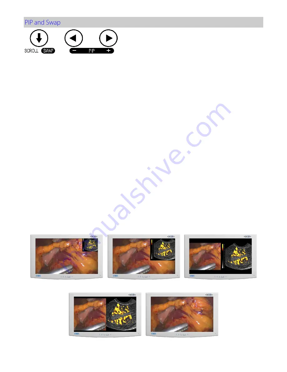
Selecting a secondary input will display a small image of the secondary source in the upper right corner of 
the display. 
  

Secondary Image Size Control 

The size of the secondary image is controlled by pressing 

 or 

► 

buttons. Pressing the 

 button will cycle 

through: 


Small PIP 

= Width of secondary image is 25% of total screen width. 


Large PIP

 = Width of secondary image is 40% of total screen width. 


Split-Screen 

= Primary and Secondary have equal width side by side (half of screen width).  


Split-Screen Overscan 

= Primary and Secondary have equal width with overscan applied 


Full Screen Primary

 = No secondary image displayed. 

The images at the bottom of the page illustrate the above sequence. 
  
Pressing the 

 button will cycle through the above sizes in reverse order. 

 
Pressing the 

SCROLL / SWAP 

button will exchange the primary and secondary inputs, and exchange their 

respective  locations  on  the  display.    Pressing  the    button  a  second  time  will  restore  the  inputs  to  their 
original  primary/secondary  status.  It  is  not  necessary  for  both  images  to  be  displayed  in  order  to  swap 
primary and secondary images.  
 
Secondary image size and image swapping may also be controlled via the GPIO port. GPIO details are on 
page 9 and the GPIO connector pin out is described on page 19. 

Split Screen 

Large PIP 

Small PIP 

Full Screen Primary


Split Screen Overscan 

Summary of Contents for Radiance G3

Page 1: ...Radiance G3 26 USER MANUAL ENGLISH ...

Page 2: ......

Page 3: ...e without notice NDS provides this information as reference only Reference to products from other vendors does not imply any recommendation or endorsement This document contains proprietary information protected by copyright No part of this manual may be reproduced by any mechanical electronic or other means in any form without prior written permission of NDS All trademarks are the property of the...

Page 4: ......

Page 5: ...ystems Overview 6 Video Source 7 PIP and Swap 8 GPIO 9 Priority Input Select 9 Display Setup 10 HD SDI Picture Menu 10 SD SDI S Video and Composite Picture Menu 10 VGA SOG RGBS and YPbPr Picture Menu 11 DVI Digital Picture Menu 12 Color Menu 13 Setup Menu 14 Defaults Menu 15 Section 6 Troubleshooting 16 Section 7 Drawing and Dimensions 17 Section 8 Data Connectors and Pinouts 18 Cable Bend Radius ...

Page 6: ...the manufacturer This symbol denotes the manufacturer s European Community representative To prevent fire or shock hazards do not expose this unit to rain or moisture Also do not use this unit s polarized plug with an extension cord receptacle or other outlets unless the prongs can be fully inserted The product is designed to meet the medical safety requirements for a patient vicinity device This ...

Page 7: ... its products through other medical device manufacturers distributors and resellers and therefore purchasers of this NDS product should consult with the entity through which this product was originally purchased regarding the terms of any applicable product warranties provided by such entity if any NDS neither assumes nor authorizes any person to assume for it any other liabilities in conjunction ...

Page 8: ......

Page 9: ...es with any subtle differences in viewing quality Intended Use This monitor is intended for use in a medical environment to display high quality video and graphic images Contraindications The monitor may not be used in the presence of flammable anesthetics mixture with air oxygen or nitrous oxide No part of this product may come in contact with a patient Never touch the product and a patient at th...

Page 10: ...ctors The VS BNC is used when the applied signal has both H sync and V sync 5 Set the REDRIVE switch to Off when the RGBS and YPbPr signals will not be daisy chained to another display The REDRIVE switch is set to On when the RGBS and YPbPr signals will be daisy chained to a second display 6 DVI 1 3G SDI 1 and S VIDEO re drives are always active when the display is powered on 7 FIBER OPTIC 90R0117...

Page 11: ... open or off side of the display s rocker switch Closed On Switch This symbol appears on the closed or on side of the display s rocker switch Equipotentiality This symbol appears next to the display s Potential Equalization Conductor ground post ...

Page 12: ...ated Select one of these inputs by pressing the keypad button under the QUICK SELECT key that points to it For example To select DVI 1 press the MENU button under the DVI 1 label If a selection is not made the QUICK SELECT menu closes after 10 seconds The QUICK SELECT menu closes 30 seconds after the last selection is made Quick Select changes only the Primary input If a Secondary input is being d...

Page 13: ...st Primary brightness When a PIP image is visible press the Brightness Contrast button again to access the Secondary brightness control Setting the brightness too high or too low will decrease the amount of visible grayscales Adjust Brightness Press the Brightness Contrast button twice three times when a PIP image is visible to display the Contrast control Press the or button to adjust Primary con...

Page 14: ... menu you want to work with then press the SCROLL button to select the parameter Press the or button to set the parameter to the desired value Press the MENU button to save your changes and close the Menu System Notes 1 All parameter names change to the language selected in the Setup menu 2 Grayed out parameters are not currently accessible Languages English Deutsch Français Italiano Svenska Españ...

Page 15: ...ssible The Input menu will automatically turn off 30 seconds after the most recent button press It may also be turned off by pressing the Input button The table below shows which inputs may be secondary when a given input is primary Inputs marked with a in the secondary column may be designated as the secondary input Inputs marked with an X in the secondary column may not be designated as the seco...

Page 16: ...ull Screen Primary No secondary image displayed The images at the bottom of the page illustrate the above sequence Pressing the button will cycle through the above sizes in reverse order Pressing the SCROLL SWAP button will exchange the primary and secondary inputs and exchange their respective locations on the display Pressing the button a second time will restore the inputs to their original pri...

Page 17: ...s the fixture s Swap button The Primary and Secondary images swap locations 5 Press the fixture s Record button the Record indicator is displayed until the Record button is released Note GPIO connector pin out is on page 19 Setup By default the Priority Input Select feature is enabled with the Primary DVI and Secondary SDI inputs preselected If the Priority Input Select feature has been disabled t...

Page 18: ...lack bars top and bottom or left and right 1 2 3 4 5 or 6 The image is linearly enlarged while remaining centered in incremental steps As the image becomes larger video information will be lost from the top and bottom and or left and right Select using or buttons Aspect SD SDI S Video and Composite only Pressing the or button changes the aspect ratio of the image from 4 3 to 16 9 or from 16 9 to 4...

Page 19: ...or 576P Fill Expands the video image to fill the entire screen The aspect ratio may not be accurately displayed Aspect Expands the video image until its largest dimension fills the screen Image may be displayed with black bars on the top and bottom or the left and right 1 1 Displays the video data in its native size and aspect ratio Image may be displayed with black bars on the top and bottom and ...

Page 20: ... the input signal is not 16 9 not interlaced and not 480P or 576P Fill Expands the video image to fill the entire screen The aspect ratio may not be accurately displayed Aspect Expands the video image until its largest dimension fills the screen Image may be displayed with black bars on the top and bottom or the left and right 1 1 Displays the video data in its native size and aspect ratio Image m...

Page 21: ...the selected color Saturation Press or to set the saturation color intensity of the image Hue Press or to set the hue color tint of the image Brightness Press the or button to adjust brightness This is a duplicate of the Brightness control described on page 5 Contrast Press the or button to adjust contrast This is a duplicate of the Contrast control described on page 5 Video Level Normal Provides ...

Page 22: ...Menu Lock Disables access to menu system This prevents inadvertent changes to the display s settings To enable Menu Lock press the or button MENU LOCKED is displayed To unlock simultaneously press and hold the MENU and SCROLL buttons until MENU UNLOCKED is displayed Communication Port This parameter allows the user choose between the display s RS 232 port or its USB ND OS port for controlling the ...

Page 23: ...olor and Setup parameters to the user s preferences 2 Select the Defaults tab 3 Use the SCROLL button to select an available User Defaults EMPTY appears in available User Defaults 4 Press the to save the user s settings The EMPTY message will be removed see User Defaults 1 in the above OSM illustration 5 Repeat steps 1 thru 4 for up to 5 users Restoring User Defaults 1 Select the User Defaults to ...

Page 24: ...uency adjustment expands or contracts the horizontal size of the displayed image The displayed image may be too wide or too narrow and vertical banding and pixel jitter may appear in grays and light colors Adjust the Frequency until the image just fits the screen Horizontal position adjustment can be used to verify that Frequency is set correctly Line up the image on the left edge of the screen an...

Page 25: ...17 ...

Page 26: ... S DATA 5 6 DDC CLOCK 21 T M D S DATA 5 7 DDC DATA 22 T M D S CLOCK SHIELD 8 ANALOG VERT SYNC DVI 2 Only 23 T M D S CLOCK 9 T M D S DATA 1 24 T M D S CLOCK 10 T M D S DATA 1 DVI2 Only 11 T M D S DATA 1 3 SHIELD C1 ANALOG RED 12 T M D S DATA 3 C2 ANALOG GREEN 13 T M D S DATA 3 C3 ANALOG BLUE 14 5V POWER C4 ANALOG HORIZ SYNC 15 GND C5 ANALOG GROUND DVI I Digital and Analog 90R0117 Only Pin Name Desc...

Page 27: ...dicator is displayed in the monitor s top left corner Pin Name Description 1 Swap Swap P S inputs 2 P S PIP Size 3 R I Record Indicator 4 GND Common Ground GPIO Mating connector RJH 4 pin Telephone Handset Serial Control Pin Name Description 1 NC No Connection 2 RXD No Connection 3 TXD Flash and Serial Control Tx 4 NC No Connection 5 GND Ground 6 NC No Connection 7 NC No Connection 8 NC No Connect...

Page 28: ...re subject to change without notice Contact factory for current specifications b Brightness shown is without a Touch Screen or A R filter installed c Applies to the Bridge Power BPM150S24F06 power supply provided with the display ...

Page 29: ...21 ...

Page 30: ...loth dampened with 80 Ethyl Alcohol Allow the unit to air dry Cautions Do not allow liquids to enter the interior of the unit and do not permit exterior surfaces to come into contact with unacceptable solvents such as those listed below as severe damage to the unit may result Acceptable Cleaning Materials Vinegar distilled white vinegar 5 acidity Ammonia based glass cleaner Acceptable Disinfecting...

Page 31: ...EMC guideline information provided in this manual and verification of all medical devices in simultaneous operation are required to ensure the electromagnetic compatibility and co existence of all other medical devices prior to a surgical procedure The EMC tables on next three pages are provided for your reference ...

Page 32: ...24 ...

Page 33: ...25 ...

Page 34: ...26 0 01 0 12 0 12 0 23 0 1 0 38 0 38 0 73 1 1 2 1 2 2 3 10 3 8 3 8 7 3 100 12 12 23 ...

Page 35: ......

Page 36: ...many 49 89 31 707 100 info novanta europe novanta com Asia Pacific Novanta Japan East Square Omori 6 20 14 Minamioi Shinagawa ku Tokyo 140 0013 Japan 81 3 5753 2466 info ndssi jp Oriental Media Center Suite 2302 Tower C No 4 Guang Hua Road Chao Yang District Beijing 100026 China 86 10 8559 7859 info ndssi com cn NDS Quality System ISO 9001 2008 and ISO 13485 2003 FDA Registration 2954921 ...

Reviews: