background image

2-20

Hardware Installation

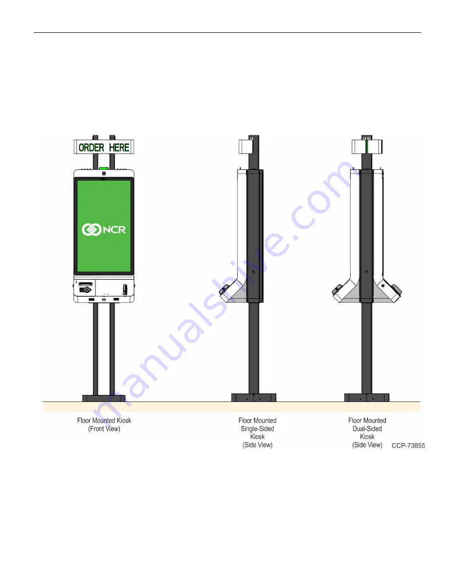
Floor Only Mounting Installation

Floor mounting installation requires the kiosk to be bolted to the floor using four
anchors. It is the responsibility of the owning institution to provide the anchors to
secure the kiosk.

For floor bolt holes and anchor details, refer to the

NCR SelfServ™ XK32 (2247) Site

Preparation

(BCC5-0000-5377).

Summary of Contents for SelfServ XK32

Page 1: ...Installation Guide NCR SelfServ XK32 2247 Kiosk Release 1 0 BCC5 0000 5246 Issue B...

Page 2: ...of an agreement you have with NCR NCR s copyright notice must be included It is the policy of NCR Corporation NCR to improve products as new technology components software and firmware become availab...

Page 3: ...rd used batteries according to the manufacturer s instructions Attention Il y a danger d explosion s il y a remplacement incorrect de la batterie Remplacer uniquement avec une batterie du m me type ou...

Page 4: ...s is the equipment grounding conductor If repair or replacement of the electric cord or plug is necessary do not connect the equipment grounding conductor to a live terminal Check with a qualified ele...

Page 5: ...or wrong components Description of failure please be specific For example display will not power on Customer Requestor s contact name phone number and or e mail address Address to ship replacement par...

Page 6: ...contact NCR Customer Services at the following numbers 1 800 262 7782 U S or Canada 1 937 445 1936 International Returning Defective Hardware for Service Use the following procedure to report return d...

Page 7: ...to HWT Brand would be assigned to Brand Direct Customer with Corporate Help Desk Log a new case on NAYS Resellers Reseller will log a new case on NAYS For assistance with the OBF process provide the f...

Page 8: ...Overview 11 Installation Guidelines and Restrictions 12 Required Tools 13 Preparing the Kiosk for Installation 14 Unpacking and Inspecting the Kiosk 15 Hardware Component Checklist 16 Installing the K...

Page 9: ...unt 119 Installing the Signage 123 Wall Mounting Installation 126 Concrete Wall Installation 127 Dry Wall with Metal C Stud Frame Installation 165 Routing and Connecting Internal Cables 203 Single Sid...

Page 10: ...routing procedures Updated AC Power and LAN cables routing procedures Updated required number of persons for kiosk installation Added procedures for unpacking and inspecting the kiosk Added perchlorat...

Page 11: ...edback interaction and an optional universal navigation uNav keypad with audio jack that is Americans with Disabilities Act ADA compliant expands accessibility to those with limitations An option from...

Page 12: ...47 5100 3001 XK32 Hospitality Kiosk Single sided i3 8 GB 120 GB SSD Printer Imager VX820 HOSP Win 10 OS uNav Wall Mount 2247 5200 1001 XK32 Hospitality Kiosk Single sided i3 8 GB 120 GB SSD Printer Im...

Page 13: ...Product Overview 1 3 Product Labels...

Page 14: ...1 4 Product Overview Configurations...

Page 15: ...projected capacitive technology that permits accurate touch detection Indicator Light Indicates whether the kiosk is in need of attention The indicator light has the following options White Light Indi...

Page 16: ...Processes credit or debit electronic payments including NFC Contactless that require a PIN The NCR SelfServ XK32 2247 Kiosk supports the following PIN pads Verifone MX915 VX820 and VX805 Ingenico iSC...

Page 17: ...rinter paper rolls or clear printer paper jams it is not required to open the kiosk The printer has its own service door see Loading Printer Paper Roll on page 236 Warning Disconnect the AC power cord...

Page 18: ...1 8 Product Overview Opening the Kiosk 1 Insert the kiosk key into the lock on the left hand side of the kiosk frame and turn the key counterclockwise to unlock the kiosk 2 Open the kiosk...

Page 19: ...Product Overview 1 9 Closing the Kiosk 1 Ensure that there are no cables that will be pinched and then close the door 2 Remove the the kiosk Key from the key lock...

Page 20: ...ect the External AC cable to totally remove power from the terminal Turning ON the Kiosk 1 Plug the External AC Power Cable to an AC power source 2 If the kiosk does not power up press the Motherboard...

Page 21: ...for damage see Unpacking and Inspecting the Kiosk on page 15 3 Install the kiosk see Installing the Kiosk on page 19 4 Route the internal cables see Routing and Connecting Internal Cables on page 203...

Page 22: ...ord can be walked on Use a grounding strap or touch a grounded metal object to discharge any static electricity from your body before servicing the terminal If the power cord is replaced it must be re...

Page 23: ...vailable Philips screwdrivers 1 2 and 3 Metric nut driver set Scissors or diagonal cutters for removing cable bindings Lifting or moving device with a toe plate of suitable length and width to fit und...

Page 24: ...ises the kiosk should be moved with its packaging intact Refer to the NCR SelfServ XK32 2247 Site Preparation BCC5 0000 5377 for details of the kiosk dimensions weights and clearances required for mov...

Page 25: ...ording the kiosk configuration 1 Verify that the NCR SelfServ XK32 2247 Kiosk model number received is the same as the model number ordered 2 Pull out the Display from the main box and place the Displ...

Page 26: ...ay Yes Yes Yes Receipt Printer Yes Yes Yes Imaging Scanner Yes Yes Yes PIN Pad Customer Supplied Yes No Yes MSR No Yes No uNav No No Yes Indicator Light No No No Camera No No No Speakers Yes Yes Yes S...

Page 27: ...Hardware Installation 2 17...

Page 28: ...2 18 Hardware Installation...

Page 29: ...hors details refer to the NCR SelfServ XK32 2247 Site Preparation BCC5 0000 5377 There are three different installation configurations for the XK32 kiosk refer to the appropriate section for the insta...

Page 30: ...stallation requires the kiosk to be bolted to the floor using four anchors It is the responsibility of the owning institution to provide the anchors to secure the kiosk For floor bolt holes and anchor...

Page 31: ...he Display on page 38 7 Install the Printer see Installing the Printer on page 47 8 If required install the PIN Pad terminals see Installing PIN Pad Terminals on page 91 9 Route the Internal Cables se...

Page 32: ...hor details refer to the NCR SelfServ XK32 2247 Site Preparation BCC5 0000 5377 To install the Floor Mount perform the following steps 1 Position the Floor Mount on the final installation location of...

Page 33: ...oles and install the four anchors a Drill four 12 mm 0 50 in holes over the marked mounting hole locations b Install four anchors into the drilled mounting holes Make sure that the tip of the anchors...

Page 34: ...2 24 Hardware Installation 4 Mount and secure the Metal Stand Legs on the anchors using four M12 nuts...

Page 35: ...Hardware Installation 2 25 Installing the Main Frame Caution Due to its weight installing the Main Frame to the Leg Stand requires at least two persons...

Page 36: ...Hardware Installation To install the Main Frame perform the following steps 1 Insert the Main Frame Assembly to the Leg Stand Caution Continue to support the frame while it is being secured to the st...

Page 37: ...Hardware Installation 2 27 2 On the bottom side secure the Main Frame to the stand plate using six M6 flathead screws...

Page 38: ...2 28 Hardware Installation 3 On the front and rear sides secure the Main Frame to the stand using six M6 combination screws on each leg...

Page 39: ...Hardware Installation 2 29 Installing the Top Poles Installing the Top Poles require the use of a step ladder or a work platform...

Page 40: ...Hardware Installation To install the Top Poles perform the following steps 1 Insert the Top Poles into the Main Frame 2 Secure the Top Poles to the Main Frame using four M6 hex head screws for each p...

Page 41: ...g the Signage Assembly requires a step ladder or a work platform For a Dual Sided Kiosk configuration there are two signage assemblies one for each side that need to be installed to the kiosk Perform...

Page 42: ...age Assembly peform the following steps 1 Install an M4 shoulder screw on the bottom signage mounting hole of each Top Pole 2 Mount the Signage to the Top Pole by hooking the bottom bracket of the Sig...

Page 43: ...Hardware Installation 2 33 3 Secure the top side of the Signage assembly using an M4 flathead screw on each side...

Page 44: ...to its weight installing the Door Assembly requires at least two persons For Dual Sided Kiosk configuration there are two Door Assemblies that require to be installed to the Kiosk Perform the procedu...

Page 45: ...Installation 2 35 To install the Door Assembly perform the following steps Caution Continue to support the Door Assembly while securing it to the kiosk 1 Partially tighten two M6 screws to the Kiosk M...

Page 46: ...2 36 Hardware Installation 2 Mount the Door Assembly to the main frame by hooking the two key hole slots on the door hinge to the two M6 screws on the main frame...

Page 47: ...Hardware Installation 2 37 3 Secure the Door Assembly using four M6 screws 4 Fully tighten the two partially installed M6 screws...

Page 48: ...Caution Due to its weight installing the Display requires at least two persons For Dual Sided Kiosk configuration there are two Displays that need to be installed to the kiosk Perform the procedure o...

Page 49: ...the following steps 1 Remove the Indicator Light and Camera cables from the cable clamp securing it to the Door Top Panel 2 Remove the Camera assembly from the kiosk by removing two M4 nuts 3 Remove t...

Page 50: ...2 40 Hardware Installation 4 Remove the Indicator Light assembly from the kiosk by removing two M4 nuts 5 Loosen the two M4 nuts securing the Top Panel...

Page 51: ...Hardware Installation 2 41 6 Remove the Top Panel by removing three M4 flat head screws 7 Partially tighten two M6 screws on the two mounting holes near the round air vent of the Display...

Page 52: ...play on the kiosk a At an angle insert the bottom part of the display into the Kiosk Door Frame b Rotate the top part of the Display into the kiosk inserting the partially mounted screws through the k...

Page 53: ...ware Installation 2 43 9 Partially install two M6 screws on the bottom mounting holes of the display Use the handles to make alignment adjustments and then tighten all four M6 screws to secure the dis...

Page 54: ...4 Hardware Installation 10 Mount the Top Panel to the kiosk by hooking the bracket on studs with partially installed nuts and then tighten the nuts 11 Secure the Top Panel using three M4 flat head scr...

Page 55: ...assembly using the two M4 nuts 13 Install the Camera assembly to the kiosk a Insert the black plastic Indicator Light Cover under the Indicator Light mounting its slots over the two studs on the Top...

Page 56: ...2 46 Hardware Installation 14 Secure the Indicator Light and Camera cables to the cable clamp on the Top Panel...

Page 57: ...nstallation 2 47 Installing the Printer For Dual Sided Kiosk configuration there are two printers that need to be installed to the kiosk Perform the procedure on each side of the kiosk to install both...

Page 58: ...bles Route the cables downward and secure them using the cable management features in the printer 2 To mount and secure the printer to the kiosk align and insert the three keyhole slots at the rear si...

Page 59: ...e install or adjust the printer as necessary a Close the Kiosk Door and check that the Door Paper Chute does not hit or press the Printer Feed Button b Open and close the Printer Service Door and chec...

Page 60: ...supports various PIN pad payment terminals from Ingenico and Verifone To install supported PIN pad payment terminals refer to the following sections Ingenico IPP320 350 on page 92 Ingenico ISC250 on...

Page 61: ...tion 2 51 Ingenico IPP320 350 1 Inside the Door Cabinet remove the two wing nuts that secure the PIN Pad Panel to the kiosk and then remove the panel 2 Remove the two screws that secure the PIN Pad pl...

Page 62: ...the panel 4 Insert the cable into the slot on top of the access hole and then mount and secure the PIN Pad plate on the panel using two screws Use the third and fifth mounting holes to secure the pla...

Page 63: ...of the panel secure the PIN Pad using the locking screw Note Use the screw packed into a small plastic bag that is taped to the front of the PIN Pad plate 7 Inside the Door Cabinet install the two win...

Page 64: ...enico ISC250 1 Inside the Door Cabinet remove the two wing nuts that secure the PIN Pad Panel to the kiosk and then remove the panel 2 Remove the two screws securing the PIN Pad Plate to the Fascia Pa...

Page 65: ...p of the access hole and then mount and secure the PIN Pad Plate on the panel using two screws Use the third and fifth mounting holes to secure the plate to the panel 5 Connect the cable to the PIN Pa...

Page 66: ...the panel lock the PIN Pad using the locking screw Note Use the locking screw packed into a small plastic bag that is taped to the front of the PIN Pad plate 8 Inside the Door Cabinet install the two...

Page 67: ...rifone MX915 1 Inside the Door Cabinet remove the two wing nuts that secure the PIN Pad Panel to the kiosk and then remove the panel 2 Remove the two screws securing the PIN Pad Plate to the Fascia Pa...

Page 68: ...of the access hole and then mount and secure the PIN Pad Plate on the panel using two screws Use the first and fourth mounting holes to secure the plate to the panel 5 Connect the cable to the PIN Pa...

Page 69: ...the panel lock the PIN Pad using the locking screw Note Use the locking screw packed into a small plastic bag that is taped to the front of the PIN Pad plate 8 Inside the Door Cabinet install the two...

Page 70: ...Installation Verifone VX805 1 Inside the Door Cabinet remove the two wing nuts that secure the PIN Pad Panel to the kiosk and then remove the panel 2 Remove the two screws that secure the PIN Pad plat...

Page 71: ...the panel 4 Insert the cable into the slot on top of the access hole and then mount and secure the PIN Pad Plate on the panel using two screws Use the second and seventh mounting holes to secure the p...

Page 72: ...of the panel secure the PIN Pad using two screws Note Use the two screws packed into a small plastic bag that is taped to the front of the PIN Pad plate 7 Inside the Door Cabinet install the two wing...

Page 73: ...llation 2 63 Verifone VX820 1 Inside the Door Cabinet remove the two wing nuts that secure the PIN Pad Panel to the kiosk and then remove the panel 2 Remove the two screws that secure the PIN Pad plat...

Page 74: ...the panel 4 Insert the cable into the slot on top of the access hole and then mount and secure the PIN Pad Plate on the panel using two screws Use the second and seventh mounting holes to secure the p...

Page 75: ...of the panel secure the PIN Pad using two screws Note Use the two screws packed into a small plastic bag that is taped to the front of the PIN Pad plate 7 Inside the Door Cabinet install the two wing...

Page 76: ...e the anchors to secure the kiosk If a False Ceiling is present an access hole needs to be cut out on the False Ceiling to pass the Ceiling Posts towards the concrete slab The Ceiling Posts need to be...

Page 77: ...see Cutting the Ceiling Posts on page 107 8 Install the Ceiling Posts see Marking and Drilling Ceiling Mounting Holes on page 112 9 Install the Ceiling Mount see Installing the Ceiling Mount on page 1...

Page 78: ...wning institution to provide the anchors to secure the kiosk For floor bolt holes and anchor details refer to the NCR SelfServ XK32 2247 Site Preparation BCC5 0000 5377 To install the Floor Mount perf...

Page 79: ...les and install the four anchors a Drill four 12 mm 0 50 in holes over the marked mounting hole locations b Install four anchors into the drilled mounting holes Make sure that the tip of the anchors d...

Page 80: ...2 70 Hardware Installation 4 Mount and secure the Metal Stand Legs on the anchors using four M12 nuts...

Page 81: ...Hardware Installation 2 71 Installing the Main Frame Caution Due to its weight installing the Main Frame to the Leg Stand requires at least two persons...

Page 82: ...Hardware Installation To install the Main Frame perform the following steps 1 Insert the Main Frame Assembly to the Leg Stand Caution Continue to support the frame while it is being secured to the st...

Page 83: ...Hardware Installation 2 73 2 On the bottom side secure the Main Frame to the stand plate using six M6 flathead screws...

Page 84: ...2 74 Hardware Installation 3 On the front and rear sides secure the Main Frame to the stand using six M6 combination screws on each leg...

Page 85: ...to its weight installing the Door Assembly requires at least two persons For Dual Sided Kiosk configuration there are two Door Assemblies that require to be installed to the Kiosk Perform the procedu...

Page 86: ...ware Installation To install the Door Assembly perform the following steps Caution Continue to support the Door Assembly while securing it to the kiosk 1 Partially tighten two M6 screws to the Kiosk M...

Page 87: ...Hardware Installation 2 77 2 Mount the Door Assembly to the main frame by hooking the two key hole slots on the door hinge to the two M6 screws on the main frame...

Page 88: ...2 78 Hardware Installation 3 Secure the Door Assembly using four M6 screws 4 Fully tighten the two partially installed M6 screws...

Page 89: ...Caution Due to its weight installing the Display requires at least two persons For Dual Sided Kiosk configuration there are two Displays that need to be installed to the kiosk Perform the procedure o...

Page 90: ...the following steps 1 Remove the Indicator Light and Camera cables from the cable clamp securing it to the Door Top Panel 2 Remove the Camera assembly from the kiosk by removing two M4 nuts 3 Remove t...

Page 91: ...Hardware Installation 2 81 4 Remove the Indicator Light assembly from the kiosk by removing two M4 nuts 5 Loosen the two M4 nuts securing the Top Panel...

Page 92: ...2 82 Hardware Installation 6 Remove the Top Panel by removing three M4 flat head screws 7 Partially tighten two M6 screws on the two mounting holes near the round air vent of the Display...

Page 93: ...play on the kiosk a At an angle insert the bottom part of the display into the Kiosk Door Frame b Rotate the top part of the Display into the kiosk inserting the partially mounted screws through the k...

Page 94: ...Hardware Installation 9 Partially install two M6 screws on the bottom mounting holes of the display Use the handles to make alignment adjustments and then tighten all four M6 screws to secure the dis...

Page 95: ...dware Installation 2 85 10 Mount the Top Panel to the kiosk by hooking the bracket on studs with partially installed nuts and then tighten the nuts 11 Secure the Top Panel using three M4 flat head scr...

Page 96: ...mbly using the two M4 nuts b Secure the Indicator Light and MEI SIL LIL cables to the cable clamps on the door Make sure that the indicator light is connected to the appropriate MEI cable connector Co...

Page 97: ...a Insert the black plastic Indicator Light Cover under the Indicator Light mounting its slots over the two studs on the Top Panel b Mount and secure the Camera assembly using two M4 nuts 14 Secure the...

Page 98: ...are Installation Installing the Printer For Dual Sided Kiosk configuration there are two printers that need to be installed to the kiosk Perform the procedure on each side of the kiosk to install both...

Page 99: ...bles Route the cables downward and secure them using the cable management features in the printer 2 To mount and secure the printer to the kiosk align and insert the three keyhole slots at the rear si...

Page 100: ...e install or adjust the printer as necessary a Close the Kiosk Door and check that the Door Paper Chute does not hit or press the Printer Feed Button b Open and close the Printer Service Door and chec...

Page 101: ...pports various PIN pad payment terminals from Ingenico and Verifone To install supported PIN pad payment terminals refer to the following sections Ingenico IPP320 350 on the next page Ingenico ISC250...

Page 102: ...tallation Ingenico IPP320 350 1 Inside the Door Cabinet remove the two wing nuts that secure the PIN Pad Panel to the kiosk and then remove the panel 2 Remove the two screws that secure the PIN Pad pl...

Page 103: ...the panel 4 Insert the cable into the slot on top of the access hole and then mount and secure the PIN Pad plate on the panel using two screws Use the third and fifth mounting holes to secure the pla...

Page 104: ...of the panel secure the PIN Pad using the locking screw Note Use the screw packed into a small plastic bag that is taped to the front of the PIN Pad plate 7 Inside the Door Cabinet install the two win...

Page 105: ...enico ISC250 1 Inside the Door Cabinet remove the two wing nuts that secure the PIN Pad Panel to the kiosk and then remove the panel 2 Remove the two screws securing the PIN Pad Plate to the Fascia Pa...

Page 106: ...p of the access hole and then mount and secure the PIN Pad Plate on the panel using two screws Use the third and fifth mounting holes to secure the plate to the panel 5 Connect the cable to the PIN Pa...

Page 107: ...the panel lock the PIN Pad using the locking screw Note Use the locking screw packed into a small plastic bag that is taped to the front of the PIN Pad plate 8 Inside the Door Cabinet install the two...

Page 108: ...rifone MX915 1 Inside the Door Cabinet remove the two wing nuts that secure the PIN Pad Panel to the kiosk and then remove the panel 2 Remove the two screws securing the PIN Pad Plate to the Fascia Pa...

Page 109: ...of the access hole and then mount and secure the PIN Pad Plate on the panel using two screws Use the first and fourth mounting holes to secure the plate to the panel 5 Connect the cable to the PIN Pa...

Page 110: ...the panel lock the PIN Pad using the locking screw Note Use the locking screw packed into a small plastic bag that is taped to the front of the PIN Pad plate 8 Inside the Door Cabinet install the two...

Page 111: ...lation 2 101 Verifone VX805 1 Inside the Door Cabinet remove the two wing nuts that secure the PIN Pad Panel to the kiosk and then remove the panel 2 Remove the two screws that secure the PIN Pad plat...

Page 112: ...the panel 4 Insert the cable into the slot on top of the access hole and then mount and secure the PIN Pad Plate on the panel using two screws Use the second and seventh mounting holes to secure the p...

Page 113: ...of the panel secure the PIN Pad using two screws Note Use the two screws packed into a small plastic bag that is taped to the front of the PIN Pad plate 7 Inside the Door Cabinet install the two wing...

Page 114: ...Installation Verifone VX820 1 Inside the Door Cabinet remove the two wing nuts that secure the PIN Pad Panel to the kiosk and then remove the panel 2 Remove the two screws that secure the PIN Pad plat...

Page 115: ...the panel 4 Insert the cable into the slot on top of the access hole and then mount and secure the PIN Pad Plate on the panel using two screws Use the second and seventh mounting holes to secure the p...

Page 116: ...of the panel secure the PIN Pad using two screws Note Use the two screws packed into a small plastic bag that is taped to the front of the PIN Pad plate 7 Inside the Door Cabinet install the two wing...

Page 117: ...needs to be cut to length A as appropriate for the Floor to Concrete Ceiling height of the installation site Refer to one of the following sections as appropriate for your height installation require...

Page 118: ...e Ceiling Posts length for Maximum Height installation 4000 mm 157 48 in For installation heights less than the maximum see Ceiling Posts for Lowered Height Installation on page 110 For a Maximum Heig...

Page 119: ...Hardware Installation 2 109 Cut off 5 mm 0 20 in from the straight edge of the Ceiling Posts and then apply rust protection paint on the edges where the cut was made...

Page 120: ...ion This section determines the appropriate Ceiling Posts length for Lowered Height installations For maximum installation height see Ceiling Posts for Maximum Height Installation on page 108 1 Determ...

Page 121: ...Hardware Installation 2 111 2 Cut off the excess length of the Ceiling Post and apply rust protection paint on the edges where the cut was made...

Page 122: ...oles Marking mounting holes for the Ceiling Mount assembly requires at least two persons and the use of a step ladder or a work platform Make sure that the Ceiling Posts are cut to the appropriate len...

Page 123: ...ill mounting holes for the Ceiling Mount perform the following steps 1 Install the Ceiling Posts to the kiosk a Insert the Ceiling Posts into the Main Frame b Secure the Ceiling Posts to the cabinet u...

Page 124: ...Mount and secure one side of the Ceiling Connector brackets to the Ceiling Pole Bracket 3 Position the Ceiling Pole Bracket assembly at the top of the Ceiling Posts a Insert the Ceiling Posts into th...

Page 125: ...15 b Mount the second side of the Ceiling Connector brackets and secure these using two screws to their opposite connector bracket c Secure the second connector bracket sides to the Ceiling Pole Brack...

Page 126: ...old the Ceiling Mount against the Concrete Ceiling slab and then mark the following mounting holes a Four mounting holes on the concrete ceiling b Eight mounting holes on each of the Ceiling Post for...

Page 127: ...k 7 Drill the four mounting holes on the ceiling and install the four anchors a Cover the kiosk to protect it from dust and debris b Drill four 12 mm 0 5 in holes over the marked mounting holes on the...

Page 128: ...2 118 Hardware Installation 8 On each Ceiling Post drill eight 3 mm 0 12 in mounting holes on the marked locations for the Ceiling Connector brackets...

Page 129: ...Hardware Installation 2 119 Installing the Ceiling Mount Installing the Ceiling Mount assembly requires at least two persons and the use of a step ladder or a work platform...

Page 130: ...To install the Ceiling Mount perform the following steps 1 Mount and secure the Ceiling Pole bracket to the anchor bolts using four M10 nuts 2 Install the Ceiling Posts to the kiosk a Insert the Ceili...

Page 131: ...to the Main Frame using four M6 hex head screws for each post 3 Secure the Ceiling Posts to the Ceiling Pole bracket using the Ceiling Connector brackets a Mount and secure the front Ceiling Connector...

Page 132: ...re Installation b Mount and secure the rear Ceiling Connector brackets using six M6 screws on each connector bracket c Secure the front and rear Ceiling Connector brackets together using four screws f...

Page 133: ...Installing the Signage Assembly requires a step ladder or a work platform For a Dual Sided Kiosk configuration there are two signage assemblies that need to be installed to the kiosk Perform the proce...

Page 134: ...age Assembly perform the following steps 1 Install an M4 shoulder screw on the bottom signage mounting hole of each Top Pole 2 Mount the Signage to the Top Pole by hooking the bottom bracket of the Si...

Page 135: ...Hardware Installation 2 125 3 Secure the top side of the Signage assembly using an M4 flathead screw on each side...

Page 136: ...hors for the kiosk Specifications for the wall and bolts are detailed in the NCR SelfServ XK32 2247 Site Preparation BCC5 0000 5377 publication Installation of the Wall Mount Configuration varies depe...

Page 137: ...o install the kiosk to a dry wall perform the following steps 1 Install the Wall Bracket to the wall see Installing the Wall Bracket Concrete on page 129 2 Install the Main Frame see Installing the Ma...

Page 138: ...Power Cord and LAN Cable on page 219 11 Verify if kiosk installation and cable routing are correct see Verifying Kiosk Installation and Cable Routing on page 233 12 Turn ON the kiosk see Turning ON th...

Page 139: ...the following steps 1 Mount the Wall Bracket on the wall a To position the Wall Bracket align the mounting holes on the Wall Bracket with the holes on the wall b Using six M10 nuts secure the Wall Bra...

Page 140: ...ardware Installation 2 Check if the Wall Bracket is evenly level a Position the spirit level on top of the Wall Bracket b Adjust the Wall Bracket so that the bubble is centered between the lines on th...

Page 141: ...Hardware Installation 2 131 3 Tighten the nuts and make sure that the Wall Bracket is firmly secured to the wall...

Page 142: ...Frame requires at least two persons 1 Mount the Main Frame assembly to the Wall Bracket by hooking the rear panel of the Main Frame to the wall bracket and aligning the locating pins on the frame pan...

Page 143: ...Installing the Top Poles Installing the Top Poles require the use of a step ladder or a work platform 1 Insert the Top Poles into the Main Cabinet 2 Secure the Top Poles to the cabinet using four M6 h...

Page 144: ...nstalling the Signage 1 Install an M4 shoulder screw on the bottom signage mounting hole of each Top Pole 2 Mount the Signage to the Top Pole by hooking the bottom bracket of the Signage to the M4 sho...

Page 145: ...Hardware Installation 2 135 3 Secure the top side of the Signage assembly using an M4 flathead screw on each side...

Page 146: ...2 136 Hardware Installation Installing the Door Assembly Caution Due to its weight installing the Door Assembly requires at least two persons 1 Partially tighten two M6 screws to the Kiosk Main Frame...

Page 147: ...Hardware Installation 2 137 2 Mount the Door Assembly to the main frame by hooking the two key hole slots on the door hinge to the two M6 screws on the main frame...

Page 148: ...2 138 Hardware Installation 3 Secure the Door Assembly using four M6 screws 4 Fully tighten the two partially installed M6 screws 5 Test the door to make sure it locks and unlocks properly...

Page 149: ...ing the Display requires at least two persons 1 Remove the Indicator Light and Camera cables from the cable clamp securing it to the Door Top Panel 2 Remove the Camera assembly from the kiosk by remov...

Page 150: ...2 140 Hardware Installation 4 Remove the Indicator Light assembly from the kiosk by removing two M4 nuts 5 Loosen the two M4 nuts securing the Top Panel...

Page 151: ...Hardware Installation 2 141 6 Remove the Top Panel by removing three M4 flat head screws 7 Partially tighten two M6 screws on the two mounting holes near the round air vent of the Display...

Page 152: ...splay on the kiosk a At an angle insert the bottom part of the display into the Kiosk Door Frame b Rotate the top part of the Display into the kiosk inserting the partially mounted screws through the...

Page 153: ...are Installation 2 143 9 Partially install two M6 screws on the bottom mounting holes of the display Use the handles to make alignment adjustments and then tighten all four M6 screws to secure the dis...

Page 154: ...4 Hardware Installation 10 Mount the Top Panel to the kiosk by hooking the bracket on studs with partially installed nuts and then tighten the nuts 11 Secure the Top Panel using three M4 flat head scr...

Page 155: ...assembly using the two M4 nuts 13 Install the Camera assembly to the kiosk a Insert the black plastic Indicator Light Cover under the Indicator Light mounting its slots over the two studs on the Top...

Page 156: ...2 146 Hardware Installation 14 Secure the Indicator Light and Camera cables to the cable clamp on the Top Panel...

Page 157: ...cables downward and secure them using the cable management features in the printer 2 To mount and secure the printer to the kiosk align and insert the three keyhole slots at the rear side of the prin...

Page 158: ...e install or adjust the printer as necessary a Close the Kiosk Door and check that the Door Paper Chute does not hit or press the Printer Feed Button b Open and close the Printer Service Door and chec...

Page 159: ...supports various PIN pad payment terminals from Ingenico and Verifone To install supported PIN pad payment terminals refer to the following sections Ingenico IPP320 350 on page 188 Ingenico ISC250 on...

Page 160: ...stallation Ingenico IPP320 350 1 Inside the Door Cabinet remove the two wing nuts that secure the PIN Pad Panel to the kiosk and then remove the panel 2 Remove the two screws that secure the PIN Pad p...

Page 161: ...n the panel 4 Insert the cable into the slot on top of the access hole and then mount and secure the PIN Pad plate on the panel using two screws Use the third and fifth mounting holes to secure the pl...

Page 162: ...of the panel secure the PIN Pad using the locking screw Note Use the screw packed into a small plastic bag that is taped to the front of the PIN Pad plate 7 Inside the Door Cabinet install the two win...

Page 163: ...genico ISC250 1 Inside the Door Cabinet remove the two wing nuts that secure the PIN Pad Panel to the kiosk and then remove the panel 2 Remove the two screws securing the PIN Pad Plate to the Fascia P...

Page 164: ...p of the access hole and then mount and secure the PIN Pad Plate on the panel using two screws Use the third and fifth mounting holes to secure the plate to the panel 5 Connect the cable to the PIN Pa...

Page 165: ...the panel lock the PIN Pad using the locking screw Note Use the locking screw packed into a small plastic bag that is taped to the front of the PIN Pad plate 8 Inside the Door Cabinet install the two...

Page 166: ...rifone MX915 1 Inside the Door Cabinet remove the two wing nuts that secure the PIN Pad Panel to the kiosk and then remove the panel 2 Remove the two screws securing the PIN Pad Plate to the Fascia Pa...

Page 167: ...p of the access hole and then mount and secure the PIN Pad Plate on the panel using two screws Use the first and fourth mounting holes to secure the plate to the panel 5 Connect the cable to the PIN P...

Page 168: ...the panel lock the PIN Pad using the locking screw Note Use the locking screw packed into a small plastic bag that is taped to the front of the PIN Pad plate 8 Inside the Door Cabinet install the two...

Page 169: ...lation 2 159 Verifone VX805 1 Inside the Door Cabinet remove the two wing nuts that secure the PIN Pad Panel to the kiosk and then remove the panel 2 Remove the two screws that secure the PIN Pad plat...

Page 170: ...the panel 4 Insert the cable into the slot on top of the access hole and then mount and secure the PIN Pad Plate on the panel using two screws Use the second and seventh mounting holes to secure the p...

Page 171: ...of the panel secure the PIN Pad using two screws Note Use the two screws packed into a small plastic bag that is taped to the front of the PIN Pad plate 7 Inside the Door Cabinet install the two wing...

Page 172: ...Installation Verifone VX820 1 Inside the Door Cabinet remove the two wing nuts that secure the PIN Pad Panel to the kiosk and then remove the panel 2 Remove the two screws that secure the PIN Pad plat...

Page 173: ...the panel 4 Insert the cable into the slot on top of the access hole and then mount and secure the PIN Pad Plate on the panel using two screws Use the second and seventh mounting holes to secure the p...

Page 174: ...of the panel secure the PIN Pad using two screws Note Use the two screws packed into a small plastic bag that is taped to the front of the PIN Pad plate 7 Inside the Door Cabinet install the two wing...

Page 175: ...7 To install the kiosk to a dry wall perform the following steps 1 Install the Wall Bracket to the wall see Installing the Wall Bracket Dry Wall on page 167 2 Install the Main Frame see Installing the...

Page 176: ...Cord and LAN Cable on page 219 11 Verify if kiosk installation and cable routing are correct see Verifying Kiosk Installation and Cable Routing on page 233 12 Turn ON the kiosk see Turning ON the Kio...

Page 177: ...erform the following steps 1 Mount the Wall Bracket on the wall a To position the Wall Bracket align the mounting holes on the Wall Bracket with the holes on the wall b Using six M10 bolts secure the...

Page 178: ...ardware Installation 2 Check if the Wall Bracket is evenly level a Position the spirit level on top of the Wall Bracket b Adjust the Wall Bracket so that the bubble is centered between the lines on th...

Page 179: ...Hardware Installation 2 169 3 Tighten the bolts and make sure that the Wall Bracket is firmly secured to the wall...

Page 180: ...Cabinet requires at least two persons 1 Mount the Main Frame assembly to the Wall Bracket by hooking the rear panel of the Main Frame to the wall bracket and aligning the locating pins on the frame pa...

Page 181: ...Installing the Top Poles Installing the Top Poles require the use of a step ladder or a work platform 1 Insert the Top Poles into the Main Cabinet 2 Secure the Top Poles to the cabinet using four M6 h...

Page 182: ...nstalling the Signage 1 Install an M4 shoulder screw on the bottom signage mounting hole of each Top Pole 2 Mount the Signage to the Top Pole by hooking the bottom bracket of the Signage to the M4 sho...

Page 183: ...Hardware Installation 2 173 3 Secure the top side of the Signage assembly using an M4 flathead screw on each side...

Page 184: ...2 174 Hardware Installation Installing the Door Assembly Caution Due to its weight installing the Door Assembly requires at least two persons 1 Partially tighten two M6 screws to the Kiosk Main Frame...

Page 185: ...Hardware Installation 2 175 2 Mount the Door Assembly to the main frame by hooking the two key hole slots on the door hinge to the two M6 screws on the main frame...

Page 186: ...2 176 Hardware Installation 3 Secure the Door Assembly using four M6 screws 4 Fully tighten the two partially installed M6 screws 5 Test the door to make sure it locks and unlocks properly...

Page 187: ...ing the Display requires at least two persons 1 Remove the Indicator Light and Camera cables from the cable clamp securing it to the Door Top Panel 2 Remove the Camera assembly from the kiosk by remov...

Page 188: ...2 178 Hardware Installation 4 Remove the Indicator Light assembly from the kiosk by removing two M4 nuts 5 Loosen the two M4 nuts securing the Top Panel...

Page 189: ...Hardware Installation 2 179 6 Remove the Top Panel by removing three M4 flat head screws 7 Partially tighten two M6 screws on the two mounting holes near the round air vent of the Display...

Page 190: ...splay on the kiosk a At an angle insert the bottom part of the display into the Kiosk Door Frame b Rotate the top part of the Display into the kiosk inserting the partially mounted screws through the...

Page 191: ...are Installation 2 181 9 Partially install two M6 screws on the bottom mounting holes of the display Use the handles to make alignment adjustments and then tighten all four M6 screws to secure the dis...

Page 192: ...2 Hardware Installation 10 Mount the Top Panel to the kiosk by hooking the bracket on studs with partially installed nuts and then tighten the nuts 11 Secure the Top Panel using three M4 flat head scr...

Page 193: ...assembly using the two M4 nuts 13 Install the Camera assembly to the kiosk a Insert the black plastic Indicator Light Cover under the Indicator Light mounting its slots over the two studs on the Top...

Page 194: ...2 184 Hardware Installation 14 Secure the Indicator Light and Camera cables to the cable clamp on the Top Panel...

Page 195: ...cables downward and secure them using the cable management features in the printer 2 To mount and secure the printer to the kiosk align and insert the three keyhole slots at the rear side of the prin...

Page 196: ...e install or adjust the printer as necessary a Close the Kiosk Door and check that the Door Paper Chute does not hit or press the Printer Feed Button b Open and close the Printer Service Door and chec...

Page 197: ...pports various PIN pad payment terminals from Ingenico and Verifone To install supported PIN pad payment terminals refer to the following sections Ingenico IPP320 350 on the next page Ingenico ISC250...

Page 198: ...stallation Ingenico IPP320 350 1 Inside the Door Cabinet remove the two wing nuts that secure the PIN Pad Panel to the kiosk and then remove the panel 2 Remove the two screws that secure the PIN Pad p...

Page 199: ...n the panel 4 Insert the cable into the slot on top of the access hole and then mount and secure the PIN Pad plate on the panel using two screws Use the third and fifth mounting holes to secure the pl...

Page 200: ...of the panel secure the PIN Pad using the locking screw Note Use the screw packed into a small plastic bag that is taped to the front of the PIN Pad plate 7 Inside the Door Cabinet install the two win...

Page 201: ...genico ISC250 1 Inside the Door Cabinet remove the two wing nuts that secure the PIN Pad Panel to the kiosk and then remove the panel 2 Remove the two screws securing the PIN Pad Plate to the Fascia P...

Page 202: ...p of the access hole and then mount and secure the PIN Pad Plate on the panel using two screws Use the third and fifth mounting holes to secure the plate to the panel 5 Connect the cable to the PIN Pa...

Page 203: ...the panel lock the PIN Pad using the locking screw Note Use the locking screw packed into a small plastic bag that is taped to the front of the PIN Pad plate 8 Inside the Door Cabinet install the two...

Page 204: ...rifone MX915 1 Inside the Door Cabinet remove the two wing nuts that secure the PIN Pad Panel to the kiosk and then remove the panel 2 Remove the two screws securing the PIN Pad Plate to the Fascia Pa...

Page 205: ...p of the access hole and then mount and secure the PIN Pad Plate on the panel using two screws Use the first and fourth mounting holes to secure the plate to the panel 5 Connect the cable to the PIN P...

Page 206: ...the panel lock the PIN Pad using the locking screw Note Use the locking screw packed into a small plastic bag that is taped to the front of the PIN Pad plate 8 Inside the Door Cabinet install the two...

Page 207: ...lation 2 197 Verifone VX805 1 Inside the Door Cabinet remove the two wing nuts that secure the PIN Pad Panel to the kiosk and then remove the panel 2 Remove the two screws that secure the PIN Pad plat...

Page 208: ...the panel 4 Insert the cable into the slot on top of the access hole and then mount and secure the PIN Pad Plate on the panel using two screws Use the second and seventh mounting holes to secure the p...

Page 209: ...of the panel secure the PIN Pad using two screws Note Use the two screws packed into a small plastic bag that is taped to the front of the PIN Pad plate 7 Inside the Door Cabinet install the two wing...

Page 210: ...Installation Verifone VX820 1 Inside the Door Cabinet remove the two wing nuts that secure the PIN Pad Panel to the kiosk and then remove the panel 2 Remove the two screws that secure the PIN Pad plat...

Page 211: ...the panel 4 Insert the cable into the slot on top of the access hole and then mount and secure the PIN Pad Plate on the panel using two screws Use the second and seventh mounting holes to secure the p...

Page 212: ...of the panel secure the PIN Pad using two screws Note Use the two screws packed into a small plastic bag that is taped to the front of the PIN Pad plate 7 Inside the Door Cabinet install the two wing...

Page 213: ...te internal cables based on kiosk configuration Single Sided Configuration refer to Single Sided Kiosk on the next page Dual Sided Configuration Primary Terminal refer to Dual Sided Primary Terminal o...

Page 214: ...ngle sided kiosk follow these steps 1 Connect the ground cables from the Door to the Main Frame Main Frame to Door Panel top side Main Frame to Door Cabinet bottom side a Insert the terminal ring of t...

Page 215: ...er ground cables to the kiosk Note The location of the ground cables depends on kiosk configuration Floor Mounted Kiosk using an M4 screw secure the ground cables to the right hand leg mount Wall Moun...

Page 216: ...ith p loops along its route c If PIN Pad is used as a payment device route the PIN Pad cable to the Ebox following the route of the bundled cables Secure the PIN Pad cable with six cables ties along i...

Page 217: ...Hardware Installation 2 207 Single Sided Kiosk with MSR Payment Device Note The MSR cable is already bundled and routed together with other internal cables...

Page 218: ...2 208 Hardware Installation Single Sided Kiosk with PIN Pad Payment Device...

Page 219: ...y terminal of a dual sided kiosk follow these steps 1 Connect the ground cables from the Door to the Main Frame Main Frame to Door Panel top side Main Frame to Door Cabinet bottom side a Insert the te...

Page 220: ...ng the LAN Cable on the lower right side of the Main Frame b Secure the bundle with p loops along its route c If PIN Pad is used as a payment device route the PIN Pad cable to the Ebox following the r...

Page 221: ...Hardware Installation 2 211 Dual Sided Kiosk with MSR Payment Device Note The MSR cable is already bundled and routed together with other internal cables...

Page 222: ...2 212 Hardware Installation Dual Sided Kiosk with PIN Pad Payment Device...

Page 223: ...ary terminal of a dual sided kiosk follow these steps 1 Connect the ground cables from the Door to the Main Frame Main Frame to Door Panel top side Main Frame to Door Cabinet bottom side a Insert the...

Page 224: ...nd secure the bundle using a cable tie Continue routing the bundle as shown in the images following this procedure d If PIN Pad is used as a payment device route the PIN Pad cable to the Ebox followin...

Page 225: ...Hardware Installation 2 215 Dual Sided Kiosk with MSR Payment Device Note The MSR cable is already bundled and routed together with other internal cables...

Page 226: ...2 216 Hardware Installation Dual Sided Kiosk with PIN Pad Payment Device...

Page 227: ...Hardware Installation 2 217 Port Assignments...

Page 228: ...Nav Keypad USB D System Fans and KIO USB E Receipt Printer USB F Ethernet LAN LAN 24V Power Supply Out 24V Power Speakers Audio Camera Camera Reserved for Wi Fi Indicator Light Trilight KIO Board Supe...

Page 229: ...r Mount Cover using floor mounted AC power outlets and LAN ports Wall mounted Kiosks require a hole in the wall with AC power outlets and LAN Ports For more information refer to the NCR SelfServ XK32...

Page 230: ...Cable 1 Connect and route the AC Power Cord a Connect the AC Power Cord to the Filter b Using a cable tie secure the cable to the adhesive cable tie mount on the Filter c Insert the cable through the...

Page 231: ...Hardware Installation 2 221 2 Insert the Primary Terminal LAN Cable through the hole on the right hand leg and route the cable downward...

Page 232: ...22 Hardware Installation 3 For a dual sided kiosk insert the Secondary Terminal LAN Cable through the hole on the other leg and route the cable downward 4 On the base plate pull out the AC and LAN cab...

Page 233: ...a power outlet and the LAN cable to a LAN port on the floor mounted power and data box 6 Mount and secure the front cover to the base plate with one screw on each side Caution Make sure that the cent...

Page 234: ...2 224 Hardware Installation 7 Mount and secure the rear cover to the base plate with one screw on each side Caution Make sure that the center panel of the cover does not pinch the AC and LAN cables...

Page 235: ...e AC Extension Cable a Connect the receptacle connector of the AC Extension Cable to the Filter b Using a cable tie secure the cable to the adhesive cable tie mount on the Filter c Insert the plug con...

Page 236: ...2 226 Hardware Installation 2 Insert the Primary Terminal LAN Cable through the hole on the right hand leg and route the cable downward...

Page 237: ...nstallation 2 227 3 For a dual sided kiosk insert the Secondary Terminal LAN Cable through the hole on the other leg and route the cable downward 4 On the base plate pull out the LAN and the AC Extens...

Page 238: ...ect the External AC Power Cable to the AC Extension Cable 6 Position the connection point of the AC Extension cable and External AC Power cable horizontally on the center front side of the legs Route...

Page 239: ...leg cover looping the cables around the center panel of the cover Caution Make sure that the center bracket of the cover does not pinch the Ethernet and AC cables 8 Mount and secure the front cover t...

Page 240: ...9 Route the cables under the access hole while mounting the rear leg cover and then secure the cover using one screw on each side Caution Make sure that the center bracket of the cover does not pinch...

Page 241: ...receptacle connector of the AC Extension Cable to the Filter b Using a cable tie secure the cable to the adhesive cable tie mount on the Filter c Insert the plug connector of the cable through the cab...

Page 242: ...2 232 Hardware Installation 2 Route the LAN cable upward through the cable access hole on the main frame and connect it to a LAN port...

Page 243: ...plemented Warning Failure to check the items indicated in this section may damage the kiosk its devices or its cables 1 Ensure that all device connectors are connected to the correct port assignments...

Page 244: ...tions The cable bundle is properly routed through the p loops No excess cable lengths are dangling Bundle and secure them with cable ties Note For details on cable routing refer to the following secti...

Page 245: ...sed No resistance is encountered when the door is closed The door latch is properly working when the door is closed 7 Ensure that all devices are working when the kiosk is turned on 8 For record purpo...

Page 246: ...soon as possible to avoid running out half way through a transaction Blinks fast The paper is out Change the paper roll immediately or data my be lost Caution Do not operate the printer or host comput...

Page 247: ...perform the following steps 1 Open the Printer Service Door a Insert the Printer Service Door key into the lock on the left hand side of the kiosk door and turn the key counterclockwise b Using the Re...

Page 248: ...inter 3 Remove the used paper roll out of the printer 4 Place the new paper roll in the paper bin with a little paper extending upward Note Ensure that the paper unrolls from the top of the roll other...

Page 249: ...Hardware Installation 2 239 5 Close the receipt cover 6 Remove excess paper by tearing it against the Cutter Blade...

Page 250: ...re Installation 7 To ensure print quality and the proper alignment of the paper press the paper feed button to advance paper Advance about 30 cm 12 in of paper 8 Tear off the excess paper against the...

Page 251: ...ardware Installation 2 241 9 Close the Printer Service Door a Slowly rotate the door upward to close the service door b Rotate the printer service key clockwise to lock the door and then emove the key...

Reviews: