background image

3-72

Installation Procedure

All cable assemblies connected to OPT Unit after being fastened to Anchor Point

27. Feed excess cabling into the electronics cavity so that the majority of the cables' slack

will be placed inside of the Dispenser Head. Re-use any existing cable restraints that
may be present. It may be necessary to use zip-ties or additional cable restraints to
secure the loose wiring.

These must be provided by the installer.

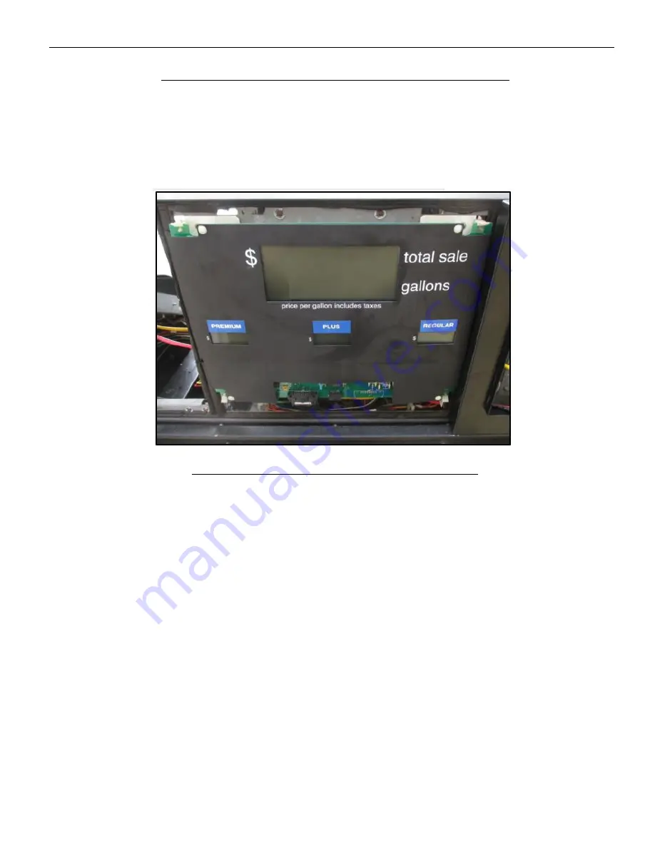
28. Re-fasten the Money/Volume Display Assembly to the Dispenser Frame.

Money/Volume Display assembly re-fastened to Dispenser Frame

Summary of Contents for OPTIC 5

Page 1: ...RETROFIT INSTALLATION GUIDE Optic 5 6001 Tokheim Premier B 6001 0008 8801 497 0513401 Issue B ...

Page 2: ... improve products as new technology components software and firmware become available NCR therefore reserves the right to change specifications without prior notice All features functions and operations described herein may not be marketed by NCR in all parts of the world In some instances photographs are of equipment prototypes Therefore before using this document consult with your NCR representa...

Page 3: ...en for end users System Administrator and Maintenance Technician NCR Field Engineering and VAR OEM Hardware and System Integrators Notice This document is NCR proprietary information and is not to be disclosed or reproduced without consent ...

Page 4: ...e these should they be required Locate the switch or circuit breakers that shut off all power to all fueling equipment and dispensing devices Total Electrical Shut Off Before Access Any procedure requiring access to electrical components or the electronics of a pump dispenser requires total electrical shut off of that unit Understand the function and location of this switch or circuit breaker befo...

Page 5: ...understand the procedures before beginning work Follow the Regulations Regulations in OSHA Occupational Safety and Health Administration national state and local codes including customer requirements must be followed Failure to install inspect maintain or service this equipment in accordance with these codes regulations and standards may lead to legal citations with penalties and may affect the sa...

Page 6: ...njury or death Signal Words Warning Alerts you to a hazard or unsafe practice which will result in death or serious injury Warning Alerts you to a hazard or unsafe practice that could result in death or serious injury Caution Designates a hazard or unsafe practice which may result in minor injury property or equipment damage Note To emphasize points or remind installer of something or to indicate ...

Page 7: ...art of defective missing wrong component Description of Failure please be specific For example display will not power on Customer Requestor s contact name phone number and or e mail address Address to ship replacement part s Transport the product n its original packaging to prevent impact damages If you do not have access to a computer you may leave a voice message at 1 800 528 8658 USA or Interna...

Page 8: ...d tear are not included in the warranty In general damages due to the following are not covered by the warranty Improper or insufficient maintenance Improper use or unauthorized modifications of the product Inadequate location or surroundings For detailed warranty arrangements please consult your contract documents ...

Page 9: ...tive equipment Equipment location in the store Description of the problem including any system error codes error condition or guidance to the area of failure The NCR Agent will provide you with a work order number which serves as your Return Material Authorization RMA Please provide the RMA on the outside of the shipping box Note A work order must be opened for each device that is shipped for repa...

Page 10: ...viii ...

Page 11: ...Upgrade Kit Contents 2 Tools Required 4 Recommended Materials 5 Chapter 2 Disassembly Procedure Wide Frame Disassembly 8 Narrow Frame Disassembly 28 Removing the Lock Assembly 45 Chapter 3 Installation Procedure Wide Frame Installation 52 Narrow Frame Installation 75 Chapter 4 Paper Loading Procedure Loading the Paper 102 ...

Page 12: ...x Revision Record Issue Date Remarks A Oct 2016 First Issue ...

Page 13: ...rovide space for the OPT mounting a power supply assembly mounting the OPT Dial Assembly and connecting the proper voltage and communication wiring assemblies The abridgement of the disassembly procedure involves removing the existing Printer Assembly Dispenser Payment Terminal DPT Module the DPT Slide Support Brackets and various cable assemblies The OPT unit reclaims the functionality of the rem...

Page 14: ...ed Dispenser Cub UL Listed by Report Retrofit Kit Part Number 6009 0008 8801 InvencoLink Converter One per dispenser to be Installed on Side A PSU Bracket Tokheim Premier B OPTIC 5 Upgrade Kit Contents Note Two kits are needed for a double sided dispenser installation Part Number QTY Description Photo Reference 497 0512466 1 Tokheim Premier B Door EMV Sub Assembly 497 0513383 1 Cat5e Data Cable 6f...

Page 15: ...ription Photo Reference 497 0514382 1 Tokheim Communications Wiring Assembly One per dispenser 497 0513525 1 Tokheim A C Wiring Assembly 497 0514448 1 Power Supply Assembly 497 0514863 1 Cushion Gasket set 497 0514641 1 Factory Lock Gasket ...

Page 16: ...Medium Flathead Screwdriver Medium Phillips Screwdriver Socket Wrench 7 16 7 8 and 3 8 Hex Socket or Nut Drivers Side Cutters or Wire Cutters 3mm Hex Driver or Allen Key Tin Snips or Sheet Metal Shears Narrow Frame Only Safety Gloves Narrow Frame Only Warning Do NOT use power tools if working on a fuel station forecourt Any spark could cause an explosion ...

Page 17: ...Introduction 1 5 Recommended Materials The following tools are not provided in the kit Cable Restraints or Zip Ties Cloth Rags All Purpose Lubricant Adhesive Remover Rust Penetrator Oil ...

Page 18: ...1 6 ...

Page 19: ...e This section provides information on the disassembly of the Optic 5 6001 Tokheim Premier B Outdoor Payment Terminal OPT The following topics are discussed Wide Frame Disassembly Narrow Frame Disassembly Removing the Lock Assembly ...

Page 20: ... all power to the dispenser and the pump servicing the dispenser Tag all disconnected breakers to prevent others from reconnecting power 3 Identify the A Side of the dispenser To determine Side A on the Premier Dispenser a Look at the base of the dispenser b Locate the Model Serial number plate on one of the dispenser sides the U L and F C C plates are nearby and stand facing it c You are looking ...

Page 21: ...d off the track and set it aside DO NOT discard the options door It will be re installed later during the Installation Procedure Note Do not discard the Options Door It will be reused during the installation process however on the opposite end left hand side of the dispenser 6 Push the Money Volume Display slide latch to completely the left to unlock the Money Volume Display Dial ...

Page 22: ...atch in lock position Latch in Unlock Position 7 Lower the Money Volume Display Dial forward lift it up and off the track and set it aside DO NOT discard the Dial It will be reused during the installation process Main Display Dial ...

Page 23: ... 2 11 Dial after removal 8 Loosen both lock screws some setups of dispensers use half turn screws others use full thread screws on the Money Volume Display Assembly then lower it by laying it forward Location of lock screws ...

Page 24: ...2 12 Disassembly Procedure Main Display Assembly Lowered 9 Unlock and lower the Printer Module Door Printer Assembly Door lowered ...

Page 25: ... lower right hand side of the module Push the top latch to the left towards left side of the dispenser completely Pull the lower latch to right towards the right side of the dispenser completely Use the following pictures as a visual aid to help locate and unlock the latches Location of upper and lower latches ...

Page 26: ...2 14 Disassembly Procedure Upper Latch viewed from behind in locked position Upper Latch viewed from behind in unlocked position ...

Page 27: ...Disassembly Procedure 2 15 Lower Latch viewed from behind in locked position Lower Latch viewed from behind in unlocked position ...

Page 28: ...ut the DPT Module 12 On the DPT board mark the Dispenser Communications wire assembly terminal J4 in order to easily identify it later during the Installation Procedure The Dispenser Communications wiring assemblies are color coded Yellow Red and Blue for Side A and Orange Brown and Green for Side B Location of Side A left and Side B right Dispenser Comm Wires ...

Page 29: ...sembly Procedure 2 17 13 Including the marked Dispenser Communications wire assembly unplug every cable assembly attached to the DPT Board as well as any other peripherals such as a keypad on the DPT Module ...

Page 30: ...y Procedure 14 Completely remove the DPT Module by pulling it out and away from the dispenser The DPT Module can be discarded It will not be re installed Dispenser after DPT has been removed DPT Assembly after removal ...

Page 31: ... the Printer Assembly forward to allow access to the Printer Assembly Cable Unplug the Printer Assembly cable Location of Printer Cable 16 Remove the Printer Assembly by pulling it away from the dispenser Printer Assembly after removal ...

Page 32: ...n be discarded It will not be re installed 19 Repeat steps 4 18 for Side B of the dispenser Note Perform this step if Side B is present Otherwise proceed to step 20 20 Remove the DPT Slide Support Bracket located on the right hand side of the dispenser a Remove the four 3 8 bolts that are securing the bracket to the frame Retain the bolts for the installation process Location of DPT Slide Support ...

Page 33: ...Disassembly Procedure 2 21 Location of the four mounting bolts ...

Page 34: ...ly Procedure b Angle and tilt the DPT Slide Support Bracket and pull it out of the dispenser cabinet Removing the DPT Slide Support Bracket c The DPT Slide Support Bracket can be discarded It will not be re installed ...

Page 35: ...card both printer cables Printer Cable after removal 22 Remove the Slide Latch Retainer Assembly a Identify the Slide Latch Retainer Assembly and Spacer Assembly located on the upper Enclosure Support Frame Location of Slide Latch Retainer Assembly ...

Page 36: ...2 24 Disassembly Procedure b Using a small flathead screwdriver pry both E style retaining rings off of the Pivot Pins Location of retaining rings Detailed image of removing retaining rings ...

Page 37: ...y removal process until all Slide Latches are uninstalled The Pivot Pins and Slide Retainers can be discarded They will not be re installed Retain the Slide Latch and hardware in the Money Volume Display location to be reinstalled Pushing the Pivot Pins through the backside of the assembly Components of Slide Latch Retainer Assembly Note Spacers and retainer clips may be present Remove from the do...

Page 38: ...er or similar tool to scrape away the old gasket material and remaining adhesive a clean flat surface is necessary to install the new gasket Note All gasket and left over adhesive material must be fully removed to ensure a clean installation surface for new gaskets during the installation procedure ...

Page 39: ...s that have been unplugged and will not be reused It is up to the discretion of the installer whether to remove these cables or position them inside of the dispenser cavity in as to not cause obstruction 25 The Disassembly Procedure is complete The dispenser is now ready for the installation of the Retrofit Kit Note For installation instructions refer to Wide Frame Installation on page 52 ...

Page 40: ...ct all power to the dispenser and the pump servicing the dispenser Tag all disconnected breakers to prevent others from reconnecting power 3 Identify the A Side of the dispenser To determine Side A on the Premier Dispenser a Look at the base of the dispenser b Locate the Model Serial number plate on one of the dispenser sides the U L and F C C plates are nearby and stand facing it c You are lookin...

Page 41: ...Disassembly Procedure 2 29 4 Identify the dispenser Modules Doors Identification of Premier B Modules 5 Unlock and open the Printer Module Door Printer Access Door opened ...

Page 42: ...er Cable Assembly 7 Remove the Printer Module Assembly by lifting it off the tracks away from the dispenser Printer Assembly after removal 8 Remove the Lock Assembly from the Printer Door Assembly Note For instructions refer to Removing the Lock Assembly on page 45 ...

Page 43: ...k the Dispenser Payment Terminal DPT by shifting the lock latch located behind the upper left hand side of the module Pull the latch to left towards the left side of the dispenser completely Use the following pictures as a visual aid to help locate and unlock the latch Location of DPT Latch Close up of latch in locked position ...

Page 44: ...2 32 Disassembly Procedure Close up of latch in unlocked position 11 Lean the DPT Module forward DPT Module opened and leaning forward ...

Page 45: ...on the rear of the DPT Module as well as any other cable assemblies that may be present on the module Location of 37 pin barrel connector 13 Remove the DPT Module by pulling it away from the dispenser The DPT Module can be discarded It will not be re installed Dispenser after DPT Removal ...

Page 46: ... lock latch to the left towards the left side of the dispenser completely The lock latch is located behind the upper left hand side of the Money Volume Display Dial Use the following pictures as a visual aid to help locate and unlock the latch Location of Money Volume Display latch in locked position ...

Page 47: ... of Money Volume latch in unlocked position 15 Lower the Money Volume Dial forward lift it off of the track and set it aside Do not discard the Money Volume Dial It will be reused during the installation process Money Volume Dial opened ...

Page 48: ... Volume Dial after removal 16 Loosen the two lock screws some setups of dispensers use half turn screws others use full thread screws that secure the Money Volume Assembly to the dispenser face Location of Sales Volume Display screws ...

Page 49: ...lume Display Assembly in fully forward position 18 Uninstall all the door slide latch retainer assemblies or Spacer Assemblies from the top of the dispenser frame a Remove the E clips from the Pivot Pins and retain Push the Pivot Pins through and retain b Uninstall the door slide latch retainer assembly ...

Page 50: ... brackets are removed the brackets and hardware that were installed where the Optic Panel will be installed can be discarded The Latch Bracket and hardware for the Money Volume Display should be retained Components of Slide Latch Retainer Assembly Note Spacers and retainer clips may be present Remove from the door ...

Page 51: ...er or similar tool to scrape away the old gasket material and remaining adhesive a clean flat surface is necessary to install the new gasket Note All gasket and left over adhesive material must be fully removed to ensure a clean installation surface for new gaskets during the installation procedure ...

Page 52: ...al especially after it s been cut can be dangerous Each cut made exposes sharp edges and creates burrs that can slice a finger Wear safety gloves whenever possible Make sure that the cut points are as flush as possible to the top and bottom of the Dispenser Electronics Cavity frame Do not leave a jagged edge or toothed cut Cut locations on the left cross brace Dispenser Electronics Cavity Frame Ex...

Page 53: ...Note Perform this step if Side B is present Otherwise proceed to step 22 22 Locate the DPT Boards Both are located behind the Printer Module Door and DPT Module on Side A of the dispenser and behind the Money Volume Display Module on Side B of the Dispenser Location of the DPT Boards mounted on DPT Bracket ...

Page 54: ...Side A left and Side B right 24 Including the marked Dispenser Communications wire assembly unplug every cable assembly attached to the DPT Board on both sides of the bracket if present Remove wires from any wire restraints to ensure easy removal of the bracket in the following steps Note Throughout this disassembly procedure there are many cable assemblies that will be unplugged and will not be r...

Page 55: ...securing the bracket to the frame Set aside for later in the installation Location of 3 8 bolts on DPT Bracket 26 Remove the DPT Bracket with the DPT Boards attached to it Bracket and board can be discarded Do not discard hardware Removing the DPT Bracket and Boards ...

Page 56: ...et mounting rails after bracket has been removed 27 The Disassembly Procedure is complete The dispenser is now ready for the installation of the Retrofit Kit Note For installation instructions refer to Narrow Frame Installation on page 75 ...

Page 57: ...sequent sub steps to properly remove the Lock Assembly Note Remove the key and make sure the lock cam is in the locked position prior to uninstalling the lock assembly 1 Set the removed Printer Module Door on a flat stable surface 2 Use a felt tipped marker or other writing utensil to mark the top of the lock cylinder indicating its orientation When the lock cylinder is re installed use this mark ...

Page 58: ...2 46 Disassembly Procedure 3 Remove the 7 16 cam nut Location of Cam Nut 4 Remove the Lock Cam ...

Page 59: ...te is seized to the Lock Cam Shaft and cannot be easily removed then it can be left in place to prevent damaging the shaft threads If the Stop Plate is left in place take care that it does not fall off or become lost Location of Stop Plate 6 Remove the 7 8 Mounting Nut Location of Mounting Nut ...

Page 60: ...2 48 Disassembly Procedure 7 Pull the Lock Cylinder through the front of the door The old seal can be discarded Lock assembly components after removal ...

Page 61: ...stallation Procedure 9 The removal of the Lock Assembly is complete Return to and continue the Disassembly Procedure step 18 for Wide Frame or step 9 for Narrow Frame Note For Wide Frame disassembly instructions refer to Wide Frame Disassembly on page 8 Note For Narrow Frame disassembly instructions refer to Narrow Frame Disassembly on page 28 ...

Page 62: ...2 50 ...

Page 63: ...tion Procedure This section provides information on the installation of the Optic 5 6001 Tokheim Premier B Outdoor Payment Terminal OPT The following topics are discussed Wide Frame Installation Narrow Frame Installation ...

Page 64: ...Supply Assembly 497 0514448 2 Install the Dispenser Cub 6009 0008 8801 onto the side A PSU bracket using the Cub Kit installation Instructions a Install the Cub on one universal Power Supply Bracket This bracket will now become the Side A PSU bracket Follow the Cub Installation Instructions 497 0514466 Acquire the Cub Retrofit Kit UL Listed by Report Retrofit kit part number 6009 0008 8801 The sec...

Page 65: ...acket Identifying Premier B Mounting plate 4 Identify the DPT Mount Rails on the right hand side of Electronics Enclosure where the DPT Slide Support bracket was removed in step 20 of the Disassembly Procedure Use both side slots not the vertical slot Location of the DPT Mount Rails as viewed from Side B ...

Page 66: ...il as shown Identifying the DPT Mount Rail and mounting holes Power Supply Assembly after installation on the Electronics Mount Rail 6 Using a 3 8 socket install the PSU bracket using the retained screw bolts to secure the Power Supply Assembly to the Electronics Mount Rail Repeat for the second side PSU ...

Page 67: ...from the kit Tokheim A C Wire Assembly 8 Insert the Large 3 Position Harness female socket of the A C Wiring Assembly into the Large 3 Position Harness male socket pigtail that is present on the Power Supply Assembly Plugging in the A C Wiring Assembly to the Power Supply Assembly ...

Page 68: ...stribution Board located on the B Side of the Dispenser and plug one end the Tokheim A C Wire Assembly into an open terminal J10 J11 J12 or J13 A C Distribution Board and terminal locations A C Wiring assembly after plugging into distribution board ...

Page 69: ... female pigtail harness on the A C Wire Assembly then plug the remaining male end of the A C Wire Assembly into the open terminal on the A C Distribution Board All terminals are occupied on dist board before installing A C Wiring assembly A C dispenser wiring assembly plugged in with existing wires attached to pigtail ...

Page 70: ...ow Cat5e Network Cable 497 0513384 and insert one end into the Optic Dispenser Cub Kit port labeled LAN1 LAN2 for Side B Lay the excess cable inside of the Electronics Cavity Installing the network cable into the LAN port on Optic Dispenser Cub Kit ...

Page 71: ...RS232 1 RS232 2 for Side B Lay the excess cable inside of the Electronics Cavity Note Due to the variety of dispenser setups it is up to the discretion of the installer how best to position installed cabling inside of the dispenser cavity so as to not cause obstruction Installing the data cable into the RS232 port on Optic Dispenser Cub Kit ...

Page 72: ... Dispenser Cub Note This procedure is only needed for Side A Tokheim Communications Wire Assembly Tokheim Communications Wire Assembly plugged into Dispenser Cub 13 Insert the opposite end of the Tokheim Communications Wire Assembly and connect it to the dispenser communications wire assembly marked in the Disassembly Procedure Note This procedure is only needed for Side A ...

Page 73: ...Installation Procedure 3 61 ...

Page 74: ...er frame as indicated in the picture below Start with the top gasket the longer of the 2 longest gaskets Install the rest of the gaskets so the top edges are flush with the bottom edge of the top gasket 15 Reinstall the Slide Latch Retainer Assembly to the Money Volume Display location a Identify the correct installation location This should be where the Money Volume Display is being reinstalled T...

Page 75: ...lide Latch Retainer Assembly c Align the brackets on the dispenser and push through the retained pivot pins from the inside Verify the latch is installed with the tab facing to the right d Reinstall the E style retaining rings to the pivot pins ...

Page 76: ...roperly 16 Acquire the OPT Premier B Dial Assembly 497 0512466 and lay it face down on a soft flat surface Caution It is recommended that the OPT Assembly is laid on top of a cloth rag to prevent any surface damage to the face of the OPT unit OPT Dial face down on a cloth rag ...

Page 77: ... front of Lock Cavity keeping in mind the mark made when the lock was removed in the Disassembly Procedure Note Make sure that the Lock Seal does not become dislodged and is present between the Lock Cylinder face and the front side of the OPT Dial Assembly Lock Cylinder inserted into Lock Cavity b Use a 7 8 deep well socket to thread the Mounting Nut onto the back side of the Lock Cylinder fasteni...

Page 78: ...t still in place Stop Plate after re installation d Insert the Lock Cam and hold it in place Secure the Lock Cam to the Lock Cylinder by re installing the 7 16 Cam Nut Lock Cam and Cam Nut after re installation e Test the lock to ensure that the orientation is correct ...

Page 79: ...Support Push the top of the dial assembly forward until it stops Lock the dial to keep it in its closed position Caution To prevent any damage make sure that ALL cable assemblies and wires are entirely inside of the Electronics Cavity before installing the OPT Dial Assembly on to the Electronics Enclosure Support Locking OPT Dial into the dispenser s Electronics Enclosure Support ...

Page 80: ...the back of the OPT Location of Tamper Prevention Plate 21 Locate one of the D C Wiring Assemblies 497 0512154 that arrive pre wired to the Power Supply Assembly Feed the open end of the cable through the opening on the tamper prevention shield and plug it into the OPT Terminal labeled VDC DC Wiring plugged into OPT Unit 22 Re fasten the tamper prevention shield to the back of the OPT ...

Page 81: ...1 for Side A RS232 2 for Side B into the OPT Ethernet terminal labeled as IOIOI Location of Red Cat5e Data Cable 24 Plug the open end of the Yellow Cat5e Network Cable the one that was plugged into terminal LAN1 for Side A LAN2 for Side B into the OPT Input Output terminal labeled as Location of Yellow Cat5e Network Cable ...

Page 82: ...Locate one of the Earth Ground Cables that arrive pre wired to the Power Supply Assembly and attach the female spade terminal to the male spade stud on the OPT unit s paper spool Earth Ground attached to spade terminal on Paper Spool ...

Page 83: ...g a zip tie gather all cable assemblies attached to the OPT unit including the Earth Ground and secure them to the Cable Restraint Anchor Point located to the left of the tamper prevention shield Location of Cable Restraint Anchor Point ...

Page 84: ... the cables slack will be placed inside of the Dispenser Head Re use any existing cable restraints that may be present It may be necessary to use zip ties or additional cable restraints to secure the loose wiring These must be provided by the installer 28 Re fasten the Money Volume Display Assembly to the Dispenser Frame Money Volume Display assembly re fastened to Dispenser Frame ...

Page 85: ...dure towards the right completely until the Money Volume Dial is secured Reach behind dial and pull latch to secure Money Volume Dial 30 Insert the bottom lip of the blank Options door into the left hand side of the Electronics Enclosure Support Push the top of the door forward until it stops and lock it using the TPX88 Key 31 Shut the OPT sub door and lock it using the supplied sub door key 32 Re...

Page 86: ...tions to ensure proper placement and good connection before re applying power Local regulations may require that the installation is electrically tested and certified BEFORE switch on Make sure all local regulations are followed properly The Retrofit Kit in a Wide Frame Premier B after installation is complete ...

Page 87: ...Supply Assembly without Optic Dispenser Cub Kit communications convertor 2 Install the Dispenser Cub 6009 0008 8801 onto the side A PSU bracket using the Cub Kit installation Instructions a Install the Cub on one universal Power Supply Bracket This bracket will now become the Side A PSU bracket Follow the Cub Installation Instructions 497 0514466 Acquire the Cub Retrofit Kit UL Listed by Report Re...

Page 88: ...on the Power Supply Assembly bracket Identifying Premier B Mounting plate 4 Facing Side A identify the outside DPT Mounting Rail where the DPT Support bracket was removed Using a 3 8 socket insert the retained mounting bolts about halfway into the designated holes as shown ...

Page 89: ...llation Procedure 3 77 5 Insert the first PSU without CUB unit Premier B mounting slot as shown facing towards the outside of the dispenser and swing it into position Use the vertical slot not the side slot ...

Page 90: ...3 78 Installation Procedure Note First PSU in final position facing towards outside of dispenser ...

Page 91: ...e retained mounting screws to secure the PSU to the Electronics Mount Rail 7 Identify the inside DPT Mounting Rail Using a 3 8 socket insert the retained 14 10 x 2 self tapping mounting screws about halfway into the designated holes as shown ...

Page 92: ...rt the second PSU with dispenser Cub in the same manner as the first PSU except facing towards the inside of the dispenser Use the vertical slot not the side slot Note Second PSU in final position facing towards inside of the dispenser ...

Page 93: ...Installation Procedure 3 81 9 Fasten the retained mounting screws to secure the PSU to the Electronics Mount Rail ...

Page 94: ...ly 497 0513525 from the kit Tokheim A C Wire Assembly 11 Insert the Large 3 Position Harness female socket of the A C Wiring Assembly into the Large 3 Position Harness male socket pigtail that is present on the Power Supply Assembly Plugging in the A C Wiring Assembly ...

Page 95: ...n Board located on the B Side of the Dispenser and plug one end the Tokheim A C Wire Assembly into an open terminal J10 J11 J12 or J13 Identifying accessible terminals on A C Distribution Board A C Distribution Board after Tokheim Wiring Assembly is installed ...

Page 96: ...o the female pigtail harness on the A C Wire Assembly then plug the remaining male end of the A C Wire Assembly into the open terminal on the A C Distribution Board All terminals are occupied on dist board before installing A C Wiring Assembly A C dist board after A C Wiring Assembly is installed and pigtailed in ...

Page 97: ...re 3 85 13 Acquire the Yellow Cat5e Network Cable 497 0513384 and insert one end into the Optic Dispenser Cub Kit port labeled LAN1 LAN2 for Side B Installing the network cable into the LAN port on Optic Dispenser Cub Kit ...

Page 98: ...RS232 1 RS232 2 for Side B Lay the excess cable inside of the Electronics Cavity Note Due to the variety of dispenser setups it is up to the discretion of the installer how best to position installed cabling inside of the dispenser cavity so as to not cause obstruction Installing the data cable into the RS232 port on Optic Dispenser Cub Kit ...

Page 99: ... Dispenser Cub Note This procedure is only needed for Side A Tokheim Communications Wire Assembly Tokheim Communications Wire Assembly plugged into Dispenser Cub 16 Insert the opposite end of the Tokheim Communications Wire Assembly and connect it to the dispenser communications wire assembly marked in the Disassembly Procedure Note This procedure is only needed for Side A ...

Page 100: ...3 88 Installation Procedure ...

Page 101: ...l the gasket along the edges of the dispenser frame as indicated in the picture below Start with the top gasket the shorter of the 2 longest gaskets Install the rest of the gaskets so the top edges are flush with the bottom edge of the top gasket Install the thinnest to the right Wide in the center and Medium to the left b When installing the thinnest right side gasket slightly lift up the custome...

Page 102: ...tch Retainer Assembly for the Money Volume Display a Identify the correct installation location This should be where the Money Volume Display is being reinsalled The latch or spacers are not needed in the OPT location b Acquire the retained latch assembly ...

Page 103: ...nents of Slide Latch Retainer Assembly c Align the brackets on the dispenser and push through the retained pivot pins from the inside Verify the latch is installed with the tab facing to the left d Reinstall the E style retaining rings ...

Page 104: ...roperly 19 Acquire the OPT Premier B Dial Assembly 497 0512466 and lay it face down on a soft flat surface Caution It is recommended that the OPT Assembly is laid on top of a cloth rag to prevent any surface damage to the face of the OPT unit OPT Dial face down on a cloth rag ...

Page 105: ...t of Lock Cavity keeping in mind the mark made when the lock was removed in step 8 of the Disassembly Procedure Note Make sure that the Lock Seal does not become dislodged and is present between the Lock Cylinder face and the front side of the OPT Dial Assembly Lock Cylinder inserted into Lock Cavity b Use a 7 8 deep well socket to thread the Mounting Nut onto the back side of the Lock Cylinder fa...

Page 106: ...if removed Stop Plate after re installation d Insert the Lock Cam and hold it in place Secure the Lock Cam to the Lock Cylinder by re installing the 7 16 Cam Nut Lock Cam and Cam Nut after re installation e Test the lock to ensure that the orientation is correct ...

Page 107: ...cs Enclosure Support Push the top of the dial assembly forward until it stops Lock the dial assembly to keep it in its closed position OPT Dial Assembly fully inserted and secure to dispenser 22 Using the supplied sub door key unlock and open the OPT sub door 23 Use a 3mm hex driver or Allen key to remove and retain the tamper prevention plate on the back of the OPT ...

Page 108: ...gh the opening on the tamper prevention shield and plug it into the OPT Terminal labeled VDC DC Wiring plugged into OPT Unit 25 Re fasten the tamper prevention shield to the back of the OPT 26 Plug the open end of the Red Cat5e Data Cable the one that was plugged into terminal RS232 1 for Side A RS232 2 for Side B into the OPT Ethernet terminal labeled as IOIOI Location of Red Cat5e Data Cable ...

Page 109: ...t5e Network Cable 28 Feed excess cabling into the electronics cavity so that the majority of the cables slack will be fastened to the inside of the Dispenser Head Re use any existing cable restraints that may be present It may be necessary to use zip ties or additional cable restraints to secure the loose wiring These must be provided by the installer 29 Re fasten the Money Volume Display Assembly...

Page 110: ...s Reach inside the OPT sub door opening and pull the Lock Latch the one that was pushed to unlock the dial in the Disassembly Procedure towards the left completely until the Money Volume Dial is secured Reach behind dial and pull latch to secure Money Volume Dial 31 Shut the OPT sub door and lock it using the supplied sub door key 32 Repeat for Side B Note Perform this step if Side B is present Ot...

Page 111: ...ions to ensure proper placement and good connection before re applying power Local regulations may require that the installation is electrically tested and certified BEFORE switch on Make sure all local regulations are followed properly The Retrofit Kit in a Narrow Frame Premier B after installation is complete ...

Page 112: ...3 100 ...

Page 113: ...Chapter 4 Paper Loading Procedure This section provides information on how to load the paper to the Optic 5 OPT printer The image below shows the rear panel of the Optic 5 OPT where the paper is loaded ...

Page 114: ...indle from the paper holder position Insert roll in place The paper tension flap is spring loaded therefore you will need to apply some pressure Insert the spindle through the middle of the roll to hold in place 3 Insert the cut edge of the paper into the slot as shown by the label Note Insert until the printer grips and feeds automatically ...

Page 115: ... 103 4 The photo shows the paper loaded correctly 5 Feed the paper to the printer To do this press either the forward or backward paper feed buttons to move the paper forwrad or back Press the buttons together to cut the paper ...

Page 116: ...4 104 Paper Loading Procedure 6 Feed the paper through the terminal until it appears at the paper exit chute Cut the paper using both feed buttons and remove the cut length from the chute ...

Reviews: