2-31
Hardware Installation
Removing the Touch and LCD Assembly
1. Remove the stand from the back of the display. For procedures, refer to
Note:
If the EX15 POS is installed with a Customer Display, disconnect the
Customer Display Cables before removing the stand.
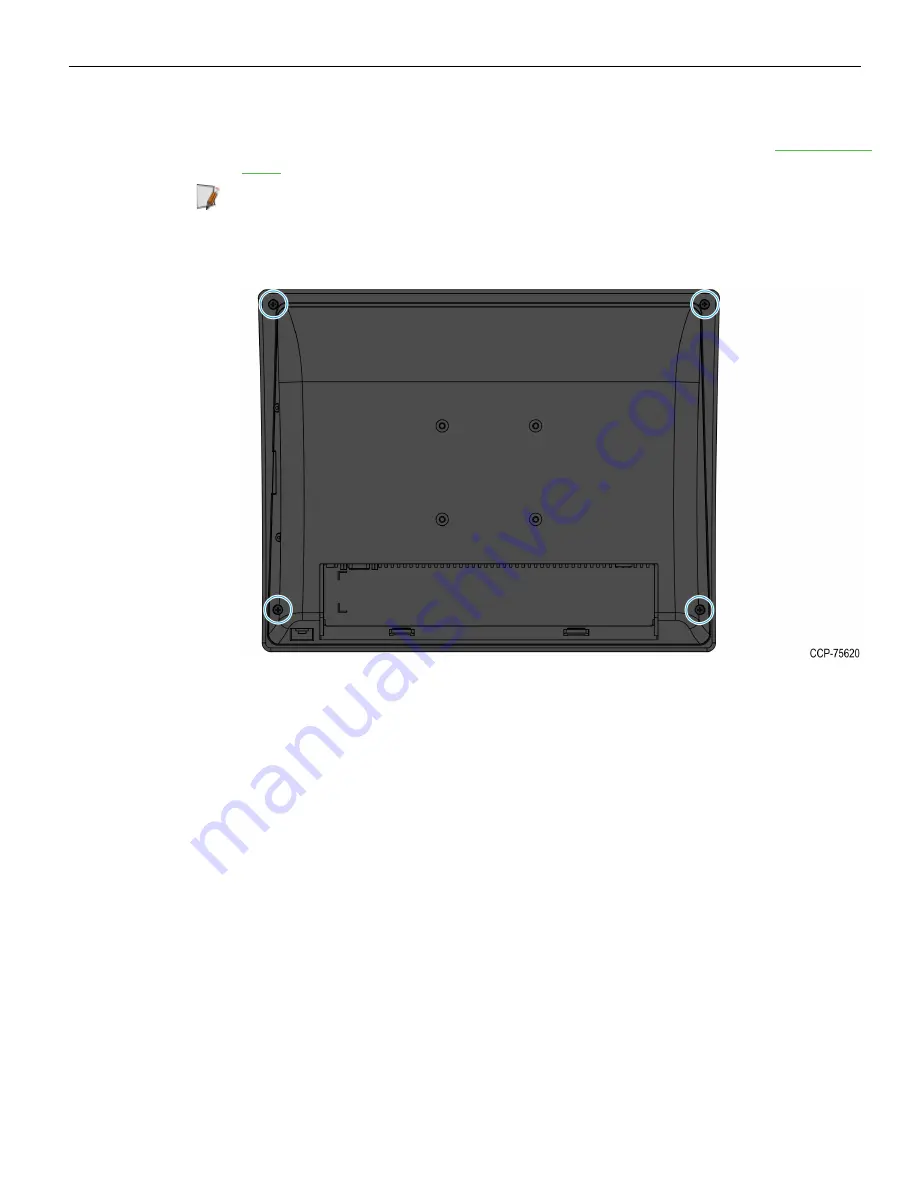
2. Remove the four screws on the back cover.
3. While holding the unit together, turn it over so that it is facing up and its peripheral
or peripheral cover is on the right side.
Summary of Contents for EX15 POS
Page 1: ...User Guide NCR EX15 POS 4505 Release 1 0 BCC5 0000 5295 Issue A...
Page 9: ...vii Chapter 5 Initial Terminal Imaging Introduction 44 Imaging Procedure 44...
Page 10: ...viii Revision Record Issue Date Remarks A Nov 2018 First Issue...
Page 16: ...1 6 Product Overview Wall Mount...
Page 17: ...Product Overview 1 7 Label Locations...
Page 50: ...4 40 BIOS Setup Setting the LCD Brightness 1 Select Advanced Video Configuration...
Page 51: ...BIOS Setup 4 41 2 Select Brightness Control Level and then select a brightness level...
Page 52: ...4 42 BIOS Setup Setting the Serial Port COM 1 Voltage 1 Select Advanced S10 FINTEX F81866A...
Page 53: ...BIOS Setup 4 43 2 Select Voltage Selector and then select OK...


