Stand, CX7
15
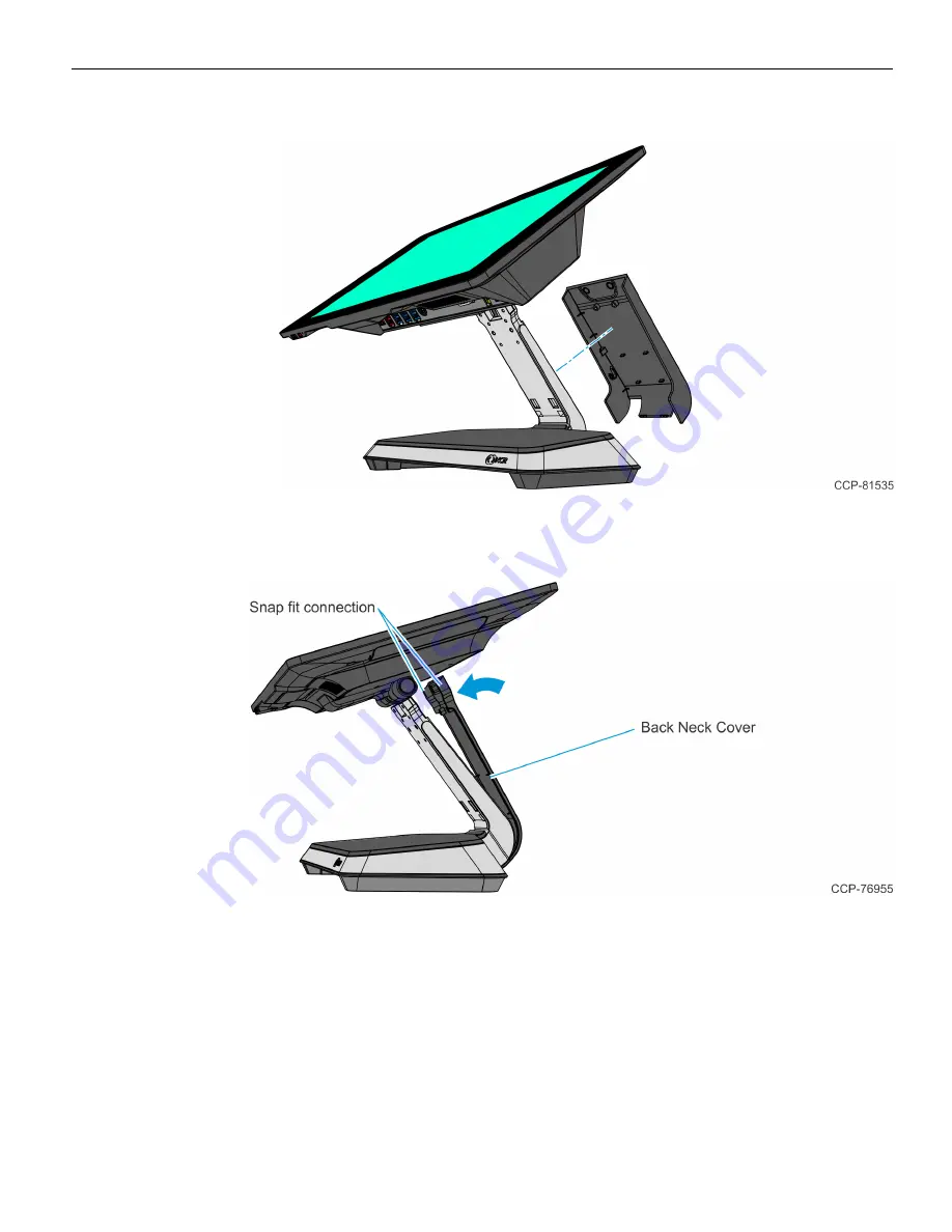
c. Remove the Neck Cover.
4. Snap the Back Neck Cover onto the neck. The Cover has a simple snap fit connection
at the top.
Page 1: ...Kit Instructions Stand CX7 7772 K030 Issue B...
Page 2: ...olicy of NCR Corporation NCR to improve products as new technology components software and firmware become available NCR therefore reserves the right to change specifications without prior notice All...
Page 3: ...Stand CX7 This kit provides a Stand for the NCR CX7 All in One POS 7772 or NCR CX5 All in One POS 7773 Kit Contents...
Page 4: ...048 Screw M3x8 SEMS Phillips Pan Head Steel Z 006 8622885 Screw M4 0 7 x 8mm Flat Head Machine Knurled Head Steel Black Oxide 006 8624893 Screw M3x5 Steel Flat Head Phillips Clear Zinc w ND Nylon Patc...
Page 5: ...C power cord from the AC outlet and wait 30 seconds before servicing the terminal 1 Install the CX7 with Integrated I O on the Bracket 4 screws Note For clarity the Neck Cover is not shown in the illu...
Page 6: ...4 Stand CX7 b Rotate the Door forward and pull out to remove 3 Connect the Cables to the I O 4 Route the Cables down the Neck as shown...
Page 7: ...stall the Neck Door a Hook the Neck Door on the Neck Cover Position the Door so that the door standoffs one on each side sit on the hooks on the inside of the neck cover one on each side b Tighten the...
Page 8: ...Power Supply Warning Disconnect the AC power cord from the AC outlet and wait 30 seconds before servicing the terminal 1 Remove the Neck Door a Loosen the two 2 thumbscrews on the Neck Door b Rotate t...
Page 9: ...Stand CX7 7 2 Slightly push the front side of the Base Cover then pivot the cover open 3 Route the AC Cord up through the opening in the Base...
Page 10: ...8 Stand CX7 4 Position the Power Supply in the recess on the Base Note The Power Supply Cable comes bundled as shown...
Page 11: ...r the Cable Management Hook 6 Route the Power Supply Cable a Route the Power Supply Cable around the Power Supply with the bundled cable in front as shown Note The Power Supply Cable should be under t...
Page 12: ...and CX7 c On the underside of the Base pull the DC Connector such that the excess cable is under the Base 7 Connect the AC Cord to the Power Supply 8 Hook the Base Cover into the Stand then snap into...
Page 13: ...and insert the DC Connector into the Power In connector on the Integrated I O 10 Reinstall the Neck Door a Hook the Neck Door on the Neck Cover Position the Door so that the door standoffs one on each...
Page 14: ...assembled stand with a wide neck cover and door to allow cable management The neck covers can be changed to the standard front neck cover 497 0523791 and back neck cover 497 0523787 which are also in...
Page 15: ...Stand CX7 13 b Rotate the Door forward and pull out to remove 2 Remove the Base Rear Foot 2 screws...
Page 16: ...14 Stand CX7 3 Remove the Neck Cover a Remove the two 2 Hex Standoffs from the Neck b Remove the two 2 screws that secure the Neck Cover to the Neck...
Page 17: ...Stand CX7 15 c Remove the Neck Cover 4 Snap the Back Neck Cover onto the neck The Cover has a simple snap fit connection at the top...
Page 18: ...e Base Rear Foot 2 screws Ensure the Neck Cover is captured under the Base Rear Foot Note The Base Rear Foot serves to manage the cables and hold the bottom of the Neck Cover in place 6 Attach the Fro...
Page 19: ...d CX7 17 7 Secure the Front Neck Cover to the Neck with two 2 screws Use the appropriate screws flat head screws for Base without Integrated Power Supply thumbscrews for Base with Integrated Power Sup...