NCR 7701-K134 Instructions Manual Download Page 7

Memory Upgrade

5

7. Press the module down until it latches in position. Make sure that the edges of the

module engage the latches and that the latches are completely engaged.

XR5 POS (7701)

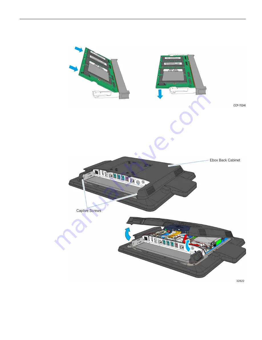
1. Remove the Rear Cover.

a. Loosen the captive screws (2) that secure it to the chassis.

b. Pivot the Rear Cover as shown.

Summary of Contents for 7701-K134

Page 1: ...Kit Instructions 4GB Memory Upgrade 7701 K134 Issue B...

Page 2: ...e become available NCR therefore reserves the right to change specifications without prior notice All features functions and operations described herein may not be marketed by NCR in all parts of the...

Page 3: ...73 Kit Contents Warning Disconnect the AC power cord before disassembling the Terminal Caution Static Electricity Discharge may permanently damage your system Discharge any static electricity build up...

Page 4: ...e Base If a Cable Management Bar is present loosen the captive screws 2 and remove the Bar 2 Remove the screws 3 securing the Bottom Cover Note An HDD storage media may be installed on the Bottom Cove...

Page 5: ...emove the front Rubber Feet 2 from the Cover 4 Carefully rotate the Cover backward to open the Base If an HDD storage media is installed remove its Data and Power connectors from the motherboard a Wit...

Page 6: ...4 Memory Upgrade b With SSD Storage Media 5 Install the memory upgrade in the right hand socket Socket 2 6 To install a module align it with the socket and push it into the socket...

Page 7: ...latches in position Make sure that the edges of the module engage the latches and that the latches are completely engaged XR5 POS 7701 1 Remove the Rear Cover a Loosen the captive screws 2 that secure...

Page 8: ...disconnect the HDD Power and Data cables from the motherboard 3 To install a module align it with the socket and push it into the socket the socket is keyed 4 Press the module down until it latches in...

Page 9: ...ded by installing a second module in the upper socket Socket 2 1 Lay the Display face down on a flat surface Note Always use a soft material cloth foam to protect the display screen when placing the t...

Page 10: ...a Loosen the thumbscrew of the 180 degree USB C Cable then disconnect the Cable b Remove the Ethernet Cable from the Cable Management Hook then disconnect the Cable 4 Remove the two 2 captive screws t...

Page 11: ...k Cover away from the Display and unhook the Back Cover Tabs 6 Install the Memory Module in the Memory Socket at an angle as shown 7 Press the Memory Module down until it latches in position Ensure th...

Page 12: ...10 Memory Upgrade 8 Insert the Back Cover Tabs into the openings in the back of the Display then rotate the Back Cover onto the Display 9 Secure the Back Cover with two 2 captive screws...

Page 13: ...the Ethernet Cable until latched and secure the cable under the Cable Management Hook b Connect the 180 degree USB C Connector and tighten the thumbscrew 11 Install the Cable Cover a Hook the bottom...

Page 14: ...12 Memory Upgrade b Secure the Cable Cover with two 2 screws...

Reviews: