background image

30

NCR RealPOS 60 Terminal Site Preparation

Customer Enclosure

Observe the following guidelines when placing the terminal inside an enclosure:

Leave at least 90 mm (3.5 in.) in the rear and 40 mm (1.5 inches) of clearance on sides
and top.

The enclosure must provide adequate ventilation.

The enclosure doors must be of a type that allows adequate airflow through the
enclosure from front to back.

The enclosure ventilation must maintain an internal temperature as close to room
ambient temperature as possible, and always below the maximum specified
operating temperature (40C / 104F).

Summary of Contents for 7601

Page 1: ...SITE PREPARATION GUIDE NCR RealPOS 60 7601 Release 2 0 B005 0000 2012 Issue C ...

Page 2: ...viceable parts Servicing should only be performed by a qualified service technician Fuse Replacement Warning For continued protection against risk of fire replace only with the same type and ratings of fuse Attention Pour prévenir et vous protéger contre un risque de feu remplacer la fusible avec une autre fusible de même type seulement Lithium Battery Warning Warning Danger of explosion if batter...

Page 3: ... must be plugged into a matching outlet that is properly installed and grounded in accordance with all local codes and ordinances Do not modify the plug provided if it will not fit the outlet have the proper outlet installed by a qualified electrician Improper connection of the equipment grounding conductor can result in a risk of electric shock The conductor with insulation having an outer surfac...

Page 4: ...iv ...

Page 5: ...l Mount Dimensions 9 VESA Mounting Hole Dimensions 10 NCR 5954 15 Inch DynaKey Dimensions 11 Standard Remote Table Top Mount 5964 K030 K031 11 NCR 5964 K038 K039 Checkstand Mount 12 NCR 5943 LCD 5967 12 Inch Touch LCD Dimensions 13 NCR 5943 LCD 5967 15 Inch Touch LCD 13 NCR 5982 6 5 Inch LCD Dimensions 14 NCR 5975 Graphical Remote Customer Display Dimensions 15 Tall Pole Mount 16 NCR 5976 Remote C...

Page 6: ... 25 Weights 26 Shipping Weight Estimate 26 Service Clearance Requirements 27 Airflow Requirements 29 Customer Enclosure 30 Electrical Requirements 31 7601 Terminal Power Requirements 31 Peripheral Power Requirements 31 AC Store Wiring Requirements 31 Cable Routing 32 Cable Cover 33 System Cables 33 Printer Cables 33 Powered USB 33 Standard USB 34 Powered USB Power Only 34 RS 232 9 Pin to 9 Pin 34 ...

Page 7: ...VGA Extension 38 Powered RS 232 5975 39 Dual Cash Drawer Y Cable 39 Ethernet 10 100 1000BaseT Cable 39 PS 2 Keyboard Extension Cable 39 RS 232 w Power 5945 5992 EPT 40 AC Power Cables 40 Appendix A TransientProtection AC Power Line Transient Protection 1 Data Line Transient Protection 2 ...

Page 8: ...viii Revision Record Issue Date Remarks A Oct 2010 First Issue B Jul 2012 Updated Solid State Optimization chapter C Jun 2013 Release 2 0 ...

Page 9: ...e terminal because site preparation deficiencies may be difficult to detect and correct after installation A NCR 7601 system consists of separate pieces combined in a variety of configurations Certain combinations are mutually exclusive You must pre determine the features and peripheral components to install before proceeding with the site preparation The system can be configured in a modular arra...

Page 10: ...is agent who is fully conversant with the special requirements of electronic equipment prepare the site The responsibility of ensuring that the site is prepared in compliance with this document remains with the customer For information and guidance purposes only a list is provided in general terms of those matters for which the customer is responsible This list does not intend to be comprehensive ...

Page 11: ...er site requirements Provide and install all communications cables wall jacks special connectors and associated hardware Provide and install necessary power distribution boxes conduits grounds lightning protection devices and associated hardware Ensure all applicable codes regulations and laws including but not limited to electrical building safety and health are met Provide and install auxiliary ...

Page 12: ...through their power cords If the peripheral is powered by the terminal and has no dedicated ground then all of the ESD energy is coupled into the port connection Some devices may require the use of an in line galvanic isolator surge protector in order to prevent problems The NCR TPP SCER process is designed to evaluate third party peripherals and determine whether additional protective devices are...

Page 13: ... the temperature changes beyond the restrictions Temperature Parameter Restriction Operating 5 C to 40 C 41 F to 104 F dry bulb Storage 10 C to 50 C 14 F to 122 F three months Shipping 40 C to 60 C 40 F to 140 F one week Humidity The terminal operates within the humidity ranges shown below Avoid continuous operation at near the indicated humidity extremes or in locations where the humidity changes...

Page 14: ...s tipped The keyboard does not attach to the drawer unit and may slide off if the drawer unit is tipped Do not turn the operator or customer displays upside down while holding only the display mounting stand The display is not attached to the stand and may slip out and be damaged if turned upside down Cabinet Security The 7601 has easy access to the internal components However the case can be secu...

Page 15: ...NCR RealPOS 60 Terminal Site Preparation 7 Dimensions NCR 7601 Terminal 7601 Terminal w Cable Cover ...

Page 16: ...8 NCR RealPOS 60 Terminal Site Preparation Vertical Mount Dimensions ...

Page 17: ...NCR RealPOS 60 Terminal Site Preparation 9 Flush Wall Mount Dimensions ...

Page 18: ...10 NCR RealPOS 60 Terminal Site Preparation VESA Mounting Hole Dimensions The bottom chassis of the 7601 has a VESA hole pattern 100 mm that can be used to mount the unit on any standard VESA mount ...

Page 19: ...NCR RealPOS 60 Terminal Site Preparation 11 NCR 5954 15 Inch DynaKey Dimensions Standard Remote Table Top Mount 5964 K030 K031 ...

Page 20: ...t The Checkstand Mount is fully adjustable between the minimum and maximum dimensions that are illustrated below The DynaKey can also be rotated right and left of center shown by approximately 90 degrees as well as tilted from a vertical position to approximately 45 degrees shown ...

Page 21: ...NCR RealPOS 60 Terminal Site Preparation 13 NCR 5943 LCD 5967 12 Inch Touch LCD Dimensions NCR 5943 LCD 5967 15 Inch Touch LCD ...

Page 22: ...14 NCR RealPOS 60 Terminal Site Preparation NCR 5982 6 5 Inch LCD Dimensions ...

Page 23: ...NCR RealPOS 60 Terminal Site Preparation 15 NCR 5975 Graphical Remote Customer Display Dimensions ...

Page 24: ... Terminal Site Preparation Tall Pole Mount There are four different length posts available for the 5975 5976 displays in four inch increments Note Heights greater than 215 mm 8 5 in should be screwed to the counter top ...

Page 25: ...NCR RealPOS 60 Terminal Site Preparation 17 NCR 5976 Remote Customer Display Dimensions ...

Page 26: ... Terminal Site Preparation Tall Pole Mount There are four different length posts available for the 5975 5976 displays in four inch increments Note Heights greater than 215 mm 8 5 in should be screwed to the counter top ...

Page 27: ...NCR RealPOS 60 Terminal Site Preparation 19 Keyboard Dimensions NCR 5932 2xxx 64 Key PS 2 POS Keyboard NCR 5932 5xxx USB Big Ticket POS Keyboard ...

Page 28: ...20 NCR RealPOS 60 Terminal Site Preparation NCR 5932 65xx PS 2 Compact Keyboard NCR 5932 66xx USB Compact Keyboard ...

Page 29: ...NCR RealPOS 60 Terminal Site Preparation 21 Printer Dimensions NCR 7167 Thermal Receipt and Impact Slip Printer NCR 7168 Thermal Receipt and Impact Slip Printer ...

Page 30: ...22 NCR RealPOS 60 Terminal Site Preparation NCR 7197 Thermal Receipt Printer NCR 7198 Thermal Receipt Printer ...

Page 31: ...NCR RealPOS 60 Terminal Site Preparation 23 Cash Drawer Dimensions NCR 2181 Cash Drawer NCR 2183 Cash Drawer ...

Page 32: ...24 NCR RealPOS 60 Terminal Site Preparation NCR 2185 Flip Top Drawer NCR 2186 Compact Cash Drawer ...

Page 33: ...NCR RealPOS 60 Terminal Site Preparation 25 Power Supply Dimensions ...

Page 34: ...r 4 5 10 0 7168 Receipt Impact Printer 5 0 11 0 7198 Thermal Receipt Printer 2 2 4 9 Shipping Weight Estimate To obtain the total maximum weight of a specific configuration add the weights of the appropriate individual components The following table provides an example Terminal Component Weight kg lbs Base unit 2 5 5 6 5942 12 1 Inch LCD Monitor 2 8 6 2 5972 Customer display 0 7 1 5 64 Key keyboar...

Page 35: ...NCR RealPOS 60 Terminal Site Preparation 27 Service Clearance Requirements ...

Page 36: ...nd mm in 7601 300 11 8 40 1 5 40 1 5 40 1 5 90 3 5 Keyboard 100 4 Cash Drawer 330 13 0 7172 Printer 325 13 300 12 0 100 4 25 1 7167 Printer 305 12 305 12 7168 Printer 305 12 305 12 7197 Printer 267 10 5 5976 2x20 Display 25 1 25 1 5943 LCD Display 50 2 25 1 5967 LCD Display 50 2 25 1 5982 LCD Display 25 1 64 2 5 ...

Page 37: ...NCR RealPOS 60 Terminal Site Preparation 29 Airflow Requirements Do not block the air vents on the terminal or peripherals These vents are necessary for cooling ...

Page 38: ... 40 mm 1 5 inches of clearance on sides and top The enclosure must provide adequate ventilation The enclosure doors must be of a type that allows adequate airflow through the enclosure from front to back The enclosure ventilation must maintain an internal temperature as close to room ambient temperature as possible and always below the maximum specified operating temperature 40C 104F ...

Page 39: ...ecific power cord must be ordered separately Available NCR power cords are described in the System Cables section Peripheral Power Requirements The number of peripherals that the terminal can support is dependent upon which peripherals are connected For planning purposes use the RealPOS 60 7601 Release 1 0 Power Matrix B005 0000 2404 for details on total power distribution Note This file requires ...

Page 40: ...32 NCR RealPOS 60 Terminal Site Preparation Cable Routing Peripheral cable connectors are located on the rear of the unit There is an additional USB port located on the front of the terminal ...

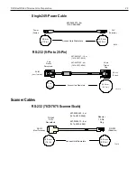
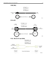
Page 41: ... the terminal can be routed down through the opening in the top of the Cable Cover External cables are routed out the bottom of the Cable Cover System Cables Printer Cables Powered USB USB Printer 24V USB Host Terminal 19307 Access Hole Diameters 23 0 mm 0 9 in 19 0 mm 0 75 in 497 0441177 1 m 1432 C088 0010 497 0473052 4 m 1432 C404 0040 ...

Page 42: ...r Only 19721 24V USB Host Terminal 23 0 mm 0 9 in 19 0 mm 0 75 in 497 0441156 1m 1432 C092 0010 497 0441157 4 m 1432 C092 0040 RS 232 9 Pin to 9 Pin 19722 9 pin D shell Receptacle 9 pin D shell Receptacle RS 232 Printer RS 232 Terminal Access Hole Diameters 38 0 mm 1 5 in 38 0 mm 1 5 in 497 0408349 0 7 m 1416 C359 0007 497 0430266 1 0 m 1416 C879 0010 497 0430265 4 m 1416 C879 0040 Black Beige ...

Page 43: ... Receptacle 25 pin D shell Plug 497 0407427 1 0 m 1416 C337 0010 497 0407429 4 m 1416 C337 0040 RS 232 Printer 63 5 mm 2 5 in Access Hole Diameters 38 mm 1 5 in RS 232 Host Terminal Scanner Cables RS 232 7872 7875 Scanner Scale 15479 RS 232 Scanner D Shell 9 Pin Receptacle Modular 10 Pin Plug 497 0300422 4 m 1416 C019 0040 497 0300423 8 m 1416 C019 0080 Access Hole Diameters 19 0 mm 0 75 in 38 0 m...

Page 44: ... 497 0418650 3 0 m 1432 C644 0030 19729 7882 Scanner RS 232 19728 Scanner D Shell 9 Pin Receptacle Modular 10 Pin Plug 497 0419723 4 0 m 1416 C653 0040 RS 232 Host Terminal Access Hole Diameters 19 0 mm 0 75 in 38 0 mm 1 5 in Display Cables USB Power 5964 5975 23434a Powered USB Display Powered USB Host Terminal 497 0445076 1 m 1432 C156 0010 497 0445077 4 m 1432 C156 0040 Access Hole Diameters 19...

Page 45: ...8 0010 497 0445079 4 m 1432 C158 0040 Access Hole Diameters 19 0 mm 0 75 in 19 0 mm 0 75 in DVI to DVI 23939a 63 5 mm 2 5 in Access Hole Diameters 497 0446721 1 0 m 1432 C191 0010 497 0446722 4 0 m 1432 C191 0040 63 5 mm 2 5 in 24 Pin DVI D Plug 24 Pin DVI D Plug DVI Host Terminal DVI Display PS 2 RS 232 Power 5964 ...

Page 46: ...2 5966 23940a Power Display 497 0428512 4 m 1416 C851 0040 Powered USB Host Terminal Access Hole Diameters 19 0 mm 0 75 in 23 0 mm 0 9 in VGA Extension 28678 Access Hole Diameters 38 0 mm 1 5 in 38 0 mm 1 5 in Sub Miniature D Shell 15 Pin Receptacle Sub Miniature D Shell 15 Pin Plug 497 0460482 4 m 1432 C298 0046 VGA Host Terminal VGA Display ...

Page 47: ...h Drawer Y Cable 15808 497 0409394 0 6 m 1416 C372 0006 Cash DWR 1 Cash DWR 2 Ethernet 10 100 1000BaseT Cable Note The 7601 supports 10 100Base T Ethernet Modular 8 Pin Plug Modular 8 Pin Plug 497 0433667 3 0 m 1432 C046 0030 22584 LAN Network LAN Host Terminal PS 2 Keyboard Extension Cable 15403 PS 2 Keyboard PS 2 Terminal 6 pin Mini DIN Plug 6 pin Mini DIN Receptacle 497 0406056 1 8 m 1416 C281 ...

Page 48: ...inal 9 pin Mini DIN Plug AC Power Cables 1416 C325 0030 006 1009037 U S The following power cables not shown also have an IEC connection of 45 mm 006 8601011 SEV 006 8601012 U K 006 8601019 Australia 006 8601010 International 006 8605488 China 006 8601001 Japan Twist Lock 1416 C320 0030 1416 C321 0030 1416 C322 0030 1416 C323 0030 1416 C391 0030 1416 C393 0030 Terminal CRT 27304a 45 mm 1 75 in Acc...

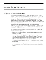
Page 49: ...ity problems are is not covered by the NCR Maintenance Agreement NCR accepts no liability for any such occurrence nor for its consequences When power transient suppression is required the suppressors used should meet the following minimum requirements Dissipate energy to match the appropriate location categories as defined by IEEE Standard C 62 41 2 2002 Be of the voltage limiting clipping or trac...

Page 50: ...ce downtime and extend the life of the RealPOS Retail Solution For sizing and product information please call NCR Site Preparation Services at 800 257 0458 The following product offerings are available from NCR Site Preparation Services UPS Uninterruptible Power Systems Provides battery backup for power outages and brownouts Includes AC and data line surge protection If needed certain models provi...

Reviews: