


1-22
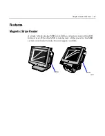
Chapter 1: Product Overview
1RWH
An external alphanumeric keyboard is recommended for
running the BIOS CMOS Setup Utility. Otherwise, a Touch Screen can
be used.
Plug and Play
The Processor BIOS also has a setup option to support the Windows
runtime plug and play utilities. When this option is selected, only
devices critical to boot are assigned resources by the BIOS. Device
Node information is available for all devices to ensure compatibility
with Windows 95. System configuration information is stored in ESCD
format. The ESCD data will be cleared upon loss of the CMOS voltage.
Advanced Power Management
The Processor BIOS has support for both 1.1 and 1.2 Advanced Power
Management (APM). The version of APM drivers loaded in the
operating system by the user will determine what specification the
BIOS will adhere too. In either case the energy saving Standby mode
can be initiated by a keyboard hot key sequence or a time-out period
set by the user.
When in Stand-by mode, the Processor Board reduces power
consumption by utilizing the processor System Management Mode
(SMM) capabilities and also spinning down hard drives and turning off
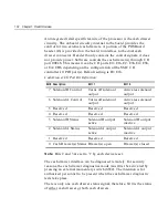
VESA DPMS compliant monitors. During setup, the user may select
which DPMS mode (Stand By, Suspend, or Off) is sent to the monitor.
The ability to respond to external interrupts is fully maintained while
in Stand-by mode allowing the system to service requests such as in-
coming data or network messages while unattended. The user may
also select any keyboard or mouse activity to take the system out of the
energy saving Standby mode. When this occurs, the monitor and IDE
drives are turned back on immediately.
APM is disabled in BIOS by default; therefore, the user must enable
this feature. The system must be configured with an APM driver in
order for the system power saving features to take effect.
Summary of Contents for 7401 Web Kiosk
Page 1: ...NCR 7401 Web Kiosk Release 2 3 Hardware User s Guide 16436 NCR B005 0000 1254 Issue D...
Page 80: ...Chapter 2 Hardware Installation 2 21 2 Remove the Core Module from the Fixed Angle Mount 16397...
Page 183: ...3 74 Chapter 3 Setup...
Page 263: ...Appendix B Feature Kits B 55 11 Route the cables in the Wall Bracket as shown below 17359...
Page 302: ...B 94 Appendix B Feature Kits 17729 Pole Mount Wall Mount...
Page 326: ...B 118 Appendix B Feature Kits 2 Insert the end of the paper into the Paper Guide 16731...
Page 328: ...B 120 Appendix B Feature Kits 4 Remove the cut paper waste from the Presenter 16965...
Page 334: ...B 126 Appendix B Feature Kits 19050...
Page 367: ...Index 159...
Page 368: ...B005 0000 1254 September 2001 Printed on recycled paper...