6
12" Pole Mount for C730 and XD10
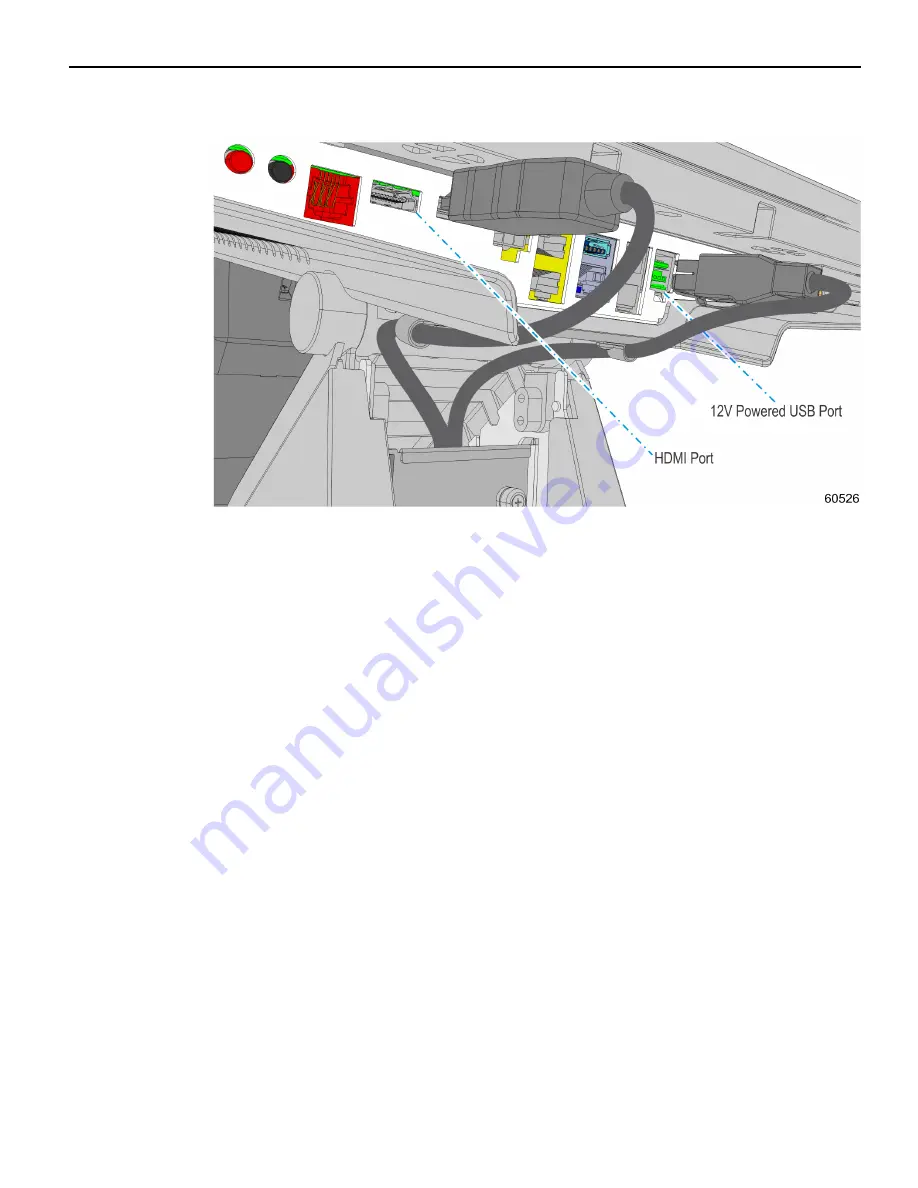
4. Connect the cables to the HDMI and 12V Powered USB ports.
5. Close and secure the CableLock Cover with the thumbscrew.
Page 1: ...KIT INSTRUCTIONS 12 Pole Mount for C730 XD10 Release 1 0 5934 K020 Issue A...
Page 2: ...with NCR NCR s copyright notice must be included It is the policy of NCR Corporation NCR to improve products as new technology components software and firmware become available NCR therefore reserves...
Page 3: ...ii Revision Record Issue Date Remarks A Mar 2017 First Issue...
Page 4: ...D10 At least one of the following Display PIDs must be ordered for this kit PID Description 5934 0419 8801 C730 No Touch No MSR Black for Pole Mount 5934 0420 8801 C730 No Touch No MSR Black with Scan...
Page 5: ...2 12 Pole Mount for C730 and XD10 Installation Procedure 1 Route the cables through the Integration Pole Secure the Integration Pole to the pole mount assembly...
Page 6: ...h the Table Top Mount 3 Secure the Table Top Mount to the countertop or integration tray with screws 4 Note The screws 4 are not included in the kit 4 Route the cables through the POS stand and connec...
Page 7: ...4 12 Pole Mount for C730 and XD10 7734 Cable Routing 1 Loosen the thumbscrew and Open the CableLock Cover 2 Route the cables under the stand and up through the CableLock Cover...
Page 8: ...0 5 3 Route the cables into the cable clamps Install the expansion blank plate and cable clamps 2 and secure with screws 2 Note If the POS includes an expansion install the cable clamps under the expa...
Page 9: ...6 12 Pole Mount for C730 and XD10 4 Connect the cables to the HDMI and 12V Powered USB ports 5 Close and secure the CableLock Cover with the thumbscrew...
Page 10: ...Mount for C730 and XD10 7 7761 7745 Cable Routing 1 Pivot the display toward the back 2 Remove the Upper Stand Cover by pivoting it away from the stand The cover has a simple snap fit connection at t...
Page 11: ...rew 4 Loosen the screw on the Terminal Cable Cover To open press down on the indentations in the Cable Cover to unlatch the cover and then pivot the cover open Note Ensure that the screw is disengaged...
Page 12: ...unt for C730 and XD10 9 6 Connect the peripheral cables to the I O Panel 7 Close the CableLock Cover and secure with thumbscrew 8 Secure the Upper Stand Cover 9 Close the Terminal Cover and secure wit...
Page 13: ...g Cables are routed out the opening in the Cable Cover and down through the Table Top Stand 1 Remove the Upper Stand Cover by pivoting it away from the stand The cover has a simple snap fit connection...
Page 14: ...12 Pole Mount for C730 and XD10 11 3 Route the cables down through the opening in the Stand Base 4 Close the Base Stand Cover and secure it with the Thumb Screw 5 Replace the Upper Stand Cover...
Page 15: ...12 12 Pole Mount for C730 and XD10 Connecting the 7702 Peripheral Cables 1 Unpack the terminal in the desired location 2 Pivot the display toward the back...
Page 16: ...on the indentations in the Cable Cover to unlatch the cover and then pivot the cover open Note If the unit has the Cable Cover Security Bracket installed you must also loosen the two captive screws be...