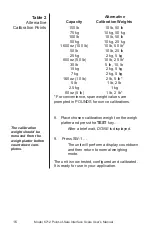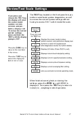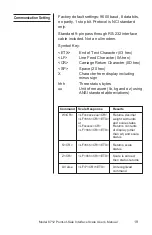
Model 6712 Point-of-Sale Interface Scale User’s Manual
18
Communication
DE-9 Female Scale
DE-9 Male Host
Pin Name Direction
Pin
Name
Direction
1.
JMP1
-
1.
DCD
IN
2.
TXD
OUT
2.
RXD
IN
3.
RXD
IN
3.
TXD
OUT
4.
JMP 1
-
4.
DTR
OUT
5.
GND
REF
5.
GND
-
6.
JMP 1
-
6.
DSR
IN
7.
JMP 2
-
7.
RTS
OUT
8.
JMP 2
-
8.
CTS
IN
9.
NC
-
9.
RI
IN
NOTE: JMP1
PINS 1, 4 and 6, and
JMP 2
Pins 7
and 8 are internally jumpered inside the scale.
Error Codes
Any system errors detected by the scale will be
displayed as the letter
E
followed by a one-digit
error code. Press the
TEST
key to continue
operation. If a calibration error occurs, the only
way to clear the error is by recalibrating the unit.
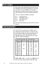
The error codes are defined as follows:
Err-1
Calibration Error
Err-2
Configuration Error
Err-3
Initial Zero Error
Err-4
Zero Error
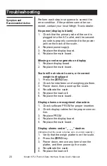
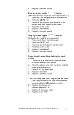
See the troubleshooting section at the end of this
manual.
The NCI 6712 comes factory configured as a
serial RS-232 interface device. There is one 9-
pin DE type female connector accessible at the
rear of the unit. The functional pinout of this
cable provided with your scale is that of a stan-
dard PC, which is as follows:

