background image


Ready To Burn


Ready To Burn: Version 1.0 October 2015 


Page 

2

 of 

24


SAFETY FIRST 


Never handle the auger, blower, nor crawl on the hopper when the system is 
powered.  There will be no warning prior to the activation of these components. 
The boiler must not be operated without the shield on the burner. 

 
The  system  is  provided  with  an  electrical  current  of  230V/50Hz.  An  improper 
installation  or  improper  repair  can  cause  life-threatening  electrical  shock. 
Electrical connections must be performed by the person who has the right skills 
and  training.  Performance  of  electrical  installation  must  be  carried  out  in 

COMPLIANCE  with  the  relevant  rules.  Always  disconnect  the  system  from  the  electrical 
supply prior to starting maintenance work or servicing. The system must be connected to a 
separate  electrical  circuit,  which  is  equipped  with  the  proper  circuit  breaker  and  earth 
leakage breaker.  

 
The boiler must be mounted to a functioning chimney. In the event that you 
smell smoke or see any other indication of improper draft of the chimney, all 
operation of your system must cease immediately and must remain so until a 
solution  to  the  draft  problem  has  been  resolved.  Continuing  operation  may 

result in death or injury.  

Always read the manual before installing and/or repairing of the system. If in 

doubt, seek professional help.  


Open top covers etc with extreme caution, there is a risk of high temperature 
below the top covers which can cause burns. Avoid handling the boiler while it 
is  in  operation.  Never  open  the  covers  or  ash  tray  while  the  boiler  is  in 
operation.  

The system must only be installed and commissioned by qualified installers. If 
you  are  in  doubt  as  to  the  safe  operational  use  of  the  boiler,  contact  your 

dealer. 


The menu structure for the controller is supported by help texts found within each section of 
the control box itself. Due to constant updates and new features, the menu structure of the 
controller will not be described here in this manual. If in doubt, never alter the settings of 
the boiler without consulting your installer. Incorrect settings will compromise the efficiency 

of the boiler and could affect any warranty cover. 

Your installer should give you a full hand over of the system and an overview of all functions 

etc. 

This manual must be kept with the boiler!  


Summary of Contents for RTB 10

Page 1: ......

Page 2: ...sion 7 boiler control system and therefore menus are not described in this manual It is recommended to study the menus before initial start up Keep this manual so you always have it available if you e...

Page 3: ...ion of your system must cease immediately and must remain so until a solution to the draft problem has been resolved Continuing operation may result in death or injury Always read the manual before in...

Page 4: ...inistrations for those countries Separate legislation the Clean Air Northern Ireland Order 1981 applies in Northern Ireland Therefore it is a requirement that fuels burnt or obtained for use in smoke...

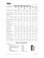
Page 5: ...nimum 24W 24W 20W 20W 34W 34W 82W 82W EN303 5 2012 Class 5 5 5 5 5 5 5 5 Controller Version V7 V7 V7 V7 V7 V7 V7 V7 Width mm 506 506 506 506 655 655 723 723 Depth mm 843 843 843 843 843 843 1043 1043...

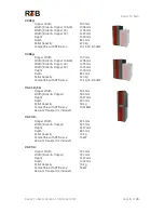
Page 6: ...23 mm Height 1300 mm Depth 845 mm Pellet Capacity 320 kg Compatible with RTB sizes 10 16 30 50kW VAC 10 16 Hopper Width 506 mm Width Boiler Hopper 506 mm Height 1827 mm Depth 845 mm Pellet Capacity 50...

Page 7: ...output 40W Weight 12kg 30kW burner Hourly fuel consumption At 25kW output 5kg Power consumption At nominal output 45W Weight 15kg 40 60kW burner Hourly fuel consumption At 50kW output 10kg Power consu...

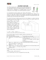
Page 8: ...ler shorten its working life and void any warranty claims The RTB boiler range is not suitable for installation outside The boiler room should be well lit with enough area to refuel the boiler and wor...

Page 9: ...ved Document J Section 2 and can meet the above requirement The heights and separation distances may have to be increased in particular cases where high wind exposure surrounding tall buildings high t...

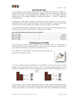
Page 10: ...ing windy conditions Recommended permanent free area vent sizes RTB 10 10kW 85cm RTB 16 17kW 144 5cm RTB 30 25kW 212 5cm RTB 50 46kW 382 5cm HYDRAULIC SYSTEM The RTB range of boiler must be installed...

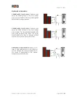
Page 11: ...d 2 DHW with 3 port valve Typically used when the DHW cylinder or the coil surface area is large The house is not supplied with heat while producing hot water The house must therefore be able to manag...

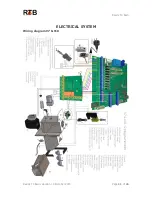
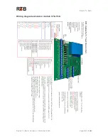
Page 12: ...Ready To Burn Ready To Burn Version 1 0 October 2015 Page 11 of 24 ELECTRICAL SYSTEM Wiring diagram V7 V10...

Page 13: ...Ready To Burn Ready To Burn Version 1 0 October 2015 Page 12 of 24 Wiring diagram extension module V7 V10...

Page 14: ...Optional output for equipment EKSTRA 3 PE N L9 Boiler Compressor Valve 1 EKSTRA 3 PE N L10 Boiler Compressor Valve 2 BUS GRD TX RX Expansion module ILT V1 V V2 O2 controller KONTAKT K K1 External ON...

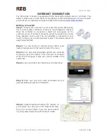
Page 15: ...t be made to the router these adapters can be used They can establish a connection to your router through your household power cables This solution allows for easy PLUG and PLAY Step 2 You can find yo...

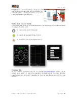
Page 16: ...ailable for the following devices This will allow you to monitor your boiler from anywhere in the world For Apple devices search StokerApp For Android devices search StokerControl For Windows devices...

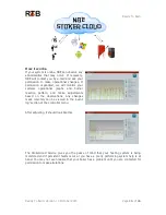
Page 17: ...nal graphs and burner reaction pattern and make adjustments based on the observations Any changes made remotely can be viewed in the event log section of the controller menu After adjusting it should...

Page 18: ...troller by going to the menu Auger Auger capacity 6 min enter pellet weight Step 2 Adjusting the Fan 1 Turn on the system by pressing the ON OFF button on the controller 2 Go to the Regulation menu se...

Page 19: ...can be easily performed Boiler All surfaces inside the boiler must be brushed clean of any deposits and the ash can must be emptied Pay special attention to any build up of ash in the rear smoke cham...

Page 20: ...Mount it correctly Too high chimney draft Install a draft stabilizer in the chimney Set electric ignition power up Reduce the fan speed during ignition Stopped fan Check if the fan can run replace if...

Page 21: ...d pipes in the installation Insulate with pipe insulation Too many electric ignitions Flow in the system is fluctuating Set the pressure controlled circulation pump to fixed pressure External thermost...

Page 22: ...ort un insulated smoke pipe 0 3 m Do not cool down the smoke unnecessarily before it reaches the chimney Draft stabilizer Stabilizes the draft and provides the chimney with dry air High boiler tempera...

Page 23: ...es where RTB UK has no influence In addition the warranty is invalid due to misuse of the burner for example using fuel that is not approved by RTB UK The warranty does not cover parts such as the ele...

Page 24: ...oduct identification Pellets Systems RTB 10 RTB10 VAC RTB 16 RTB16 VAC RTB 30 RTB 30 VAC RTB 50 RTB 50 VAC is in conformity with the provisions of the following EC directive s including all applicable...

Page 25: ...esh air intake building regs part J Y N Air intake size cm 11 Has the system been quick calibrated by weighing the pellets Y N Weight of pellets in 6 minutes g 12 Has the client been informed about th...

Reviews: