background image

89

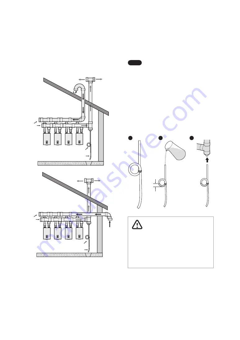
Installing a Common Vent System

To install a condensate drain to the common vent 

system:

1.  Form a loop with a drain hose and fix it with a 

tie.

Note


 While shaping the hose, do not 

bend the hose excessively. The hose 

will be deformed and the flow will be 

restricted if the hose is bent in sharp 

angles.


Do not fix the hose too tight when 

tying the hose to form the loop. The 

hose will be deformed and the flow 

will be restricted if the tie is too tight.

2.  Prime the loop using tap water.

3.  Install the hose to the common vent system and 

direct the end of the hose to a drain.

   7.9 in

(200 mm)

WARNING

After installing the condensate drain hose, 

check the loop again to ensure that the prime 

water is not spilled. The loop (siphon) must be 

primed with water before running the system 

to prevent toxic exhaust gas from leaking into 

the installation site.

9.7    Installing a Condensate Drain

Refer to the following examples to install a condensate 

drain hose (field supplied) to the common vent system. 

The condensate drain hose prevents condensate or 

rain from entering the exhaust system and gathering 

above the backflow damper.

Exhaust

Intake

End

Cap

Siphon loop

Drain hose

Exhaust

Intake

End

Cap

Drain

Siphon loop

Drain hose

Drain

Summary of Contents for NFB-175H

Page 1: ...ly call your gas supplier from a neighbor s phone Follow the gas supplier s instructions If you cannot reach your gas supplier call the fire department Installation and service must be performed by a...

Page 2: ...located in a crawl space unless the appliance is located in a detached uninhabitable garage For all residential dwellings a carbon monoxide detector must also be present on each habitable level of th...

Page 3: ...Sensor 126 12 5 Outdoor Reset Control 126 12 6 Component Assembly Diagrams and Parts Lists 128 1 About the Boiler 6 1 1 Included Items 6 1 2 Accessories 6 1 3 Specifications 7 1 4 Components 9 1 5 Di...

Page 4: ...bor s phone call your gas provider and follow their instructions If you cannot reach your gas provider call the fire department Do not return to your home until authorized by your gas supplier or the...

Page 5: ...als such as a clothes line that could obstruct the air flow in or out of the boiler This boiler has been approved for use in the USA and Canada only Using the boiler in any other country will void the...

Page 6: ...Gas Only Outdoor Temperature Sensor and Cable Air Vent Bushing 3 4in to 1 2in Condensate Trap Universal Temperature Sensor Spare Parts High Altitude Conversion kit and Propane Conversion kit are atta...

Page 7: ...RI Rating Water3 MBH AFUE2 Water Pressure Water Connection Size Supply Return Water Volume Min Max NFB 175H 13 3 175 160 139 95 6 80 psi 1 in NPT 4 5 Gallon NFB 200H 199 182 158 95 Note 1 Ratings are...

Page 8: ...el Heat Exchangers Stainless Steel Venting Exhaust 2 in or 3 in PVC CPVC approved polypropylene 2 in or 3 in Special Gas Vent Type BH Class III A B C 2 in or 3 in Stainless Steel Intake 2 in or 3 in P...

Page 9: ...endixes Intake Air Air Intake Pipe Vent Installation Detector Exhaust Duct Fan Motor Assembly Dual Venturi APS PCB Power Switch Air Vent Connection Gas Pipe Mixing Chamber Igniter Flame Rod Fire Tube...

Page 10: ...re Tube Type Heat Exchanger APS Power Switch Heating Return Gas Inlet Gas Valve ASME Name Plate Mixing Chamber Air Intake Filter Flame Rod Igniter Transformer Igniter 24 V Power Transformer Heating Su...

Page 11: ...ply Connections Description Diameter A Air Intake 2 in B Exhaust Gas Vent 2 in C Air Vent Connection 3 4 in D Heating Supply 11 4 in E Heating Return 11 4 in F Gas Connection 3 4 in G Condensate Outle...

Page 12: ...do not install the boiler If conversion to Propane Gas is required the included gas conversion kit must be used Refer to 12 1 Gas High Altitude Conversion on page 117 for details WARNING Ensure that t...

Page 13: ...container Removing theWood Pallet and the Pallet Brackets 1 Loosen the six screws that secure the wood pallet on the bottom left and right sides of the boiler 2 Remove the wood pallet the upper contai...

Page 14: ...tion code for hydronic heating systems and any local codes Access to Utilities Water the installation location should be near where the domestic water supply enters the building Gas the installation l...

Page 15: ...result in damage to the area adjacent to the appliance or to lower floors of the structure When such locations cannot be found installation of an adequately drained drain pan under the boiler is highl...

Page 16: ...e with natural gas and propane Refer to 6 Setting the DIP Switches on page 69 for the appropriate altitude setting 2 3 Mounting the Boiler to the Wall Navien NFB H boilers come with an upper mounting...

Page 17: ...on its back or put it inside the protective shipping base Install the boiler in the upright vertical position Installation in any other orientation will result in improper boiler operation and proper...

Page 18: ...and to avoid heat exchanger failure it is critical to ensure the rules and guidelines in this section are followed CAUTION Failure to follow the instructions provided in this section will void the wa...

Page 19: ...ments System Pressure The Navien NFB H boiler is intended solely for use in pressurized closed loop heating systems operating with 12 80 psi water pressure at the boiler outlet To obtain the minimum s...

Page 20: ...instructions and guidelines when installing the pressure relief valve The valve should be installed only by a licensed professional The pressure relief valve must be installed at the boiler outlet and...

Page 21: ...g the pressure relief valve follow these guidelines Ensure that the valve s discharge capacity is equal to or greater than the maximum pressure rating of the boiler s space heating system Ensure that...

Page 22: ...rundfos Taco Bell Gossett Armstrong NFB 175H 20 F UPS26 99FC 0010 IFC 0013 MSF1 IFC NRF 36 E7 25 F UPS26 99FC 0010 IFC 0015 MSF1 IFC NRF 25 E7 35 F UPS15 58FC 005 IFC 0015 MSF1 IFC NRF 22 Astro 30 NFB...

Page 23: ...1 1 2 3 4 3 5 6 7 4 9 2 11 5 Maximum and Minimum Flow Rates through the Boiler Model Minimum Pipe Diameter Maximum Flow GPM Minimum Flow GPM NFB 175H 11 4 23 1 7 0 NFB 200H 11 4 26 4 8 0 Temperature...

Page 24: ...glycol 35 F T 30 glycol Flow Rate GPM Head Ft Flow Rate GPM Head Ft Flow Rate GPM Head Ft NFB 175H 17 6 0 14 4 0 10 2 2 NFB 200H 20 7 7 16 5 0 11 2 6 Model 20 F T 50 glycol 25 F T 50 glycol 35 F T 50...

Page 25: ...tion has an acidic pH of 3 5 Follow all local codes and regulations when disposing of condensate from the boiler We recommend draining the condensate into a suitable external drain However other suita...

Page 26: ...nto an external drain Note Do not install a fixed connection for the drain b From the boiler through a neutralizing agent and then into an external drain refer to 3 2 1 Condensate Neutralizer Kit on p...

Page 27: ...sate into the appliance Do not connect more than one appliance to the neutralizer If option b p 25 is selected as the disposal option the Navien condensate neutralizer kit is recommended The condensat...

Page 28: ...s full Vent Screw Air Vent Cap Note Ensure that the vent cap is re installed and the vent screws on the system and boiler pumps are properly tightened before testing or operating the system Figure 2 V...

Page 29: ...l vary with each application The typical cold water fill pressure for a residential system is 12 psi The pressure will rise when the boiler is turned on and the system water temperature increases The...

Page 30: ...me isolated from the boiler anytime the system is operating Failure to follow these instructions may lead to discharge from the pressure relief valve which may result in property damage or injury Note...

Page 31: ...following examples to properly implement a system for space heating DHW supply or both These examples are provided to suggest basic guidelines when you install the boiler system However the actual ins...

Page 32: ...ication drawings are intended to explain the system piping concept only Install a filter in the system return to remove foreign objects from the system Foreign objects inside the system may result in...

Page 33: ...re intended to explain the system piping concept only Install a filter in the system return to remove foreign objects from the system Foreign objects inside the system may result in abnormal system op...

Page 34: ...system Foreign objects inside the system may result in abnormal system operation Refer to 3 3 Filling the System on page 28 for make up water connections and refer to the requirements of your local c...

Page 35: ...re intended to explain the system piping concept only Install a filter in the system return to remove foreign objects from the system Foreign objects inside the system may result in abnormal system op...

Page 36: ...work on the controls Wiring errors can cause abnormal and dangerous operation Verify proper operation after servicing Note The installation must comply with National Electrical Code and any other nati...

Page 37: ...SUPPLY RETURN OUTDOOR DHW TANK AC24VL LWCO R W C R W C R W C R W C COM A H DHW PRI NO NC N L N L N L Zone pump 1 max 2 5 A Zone pump 2 max 2 5 A Zone pump 3 max 2 5 A Boiler pump max 2 5 A LWCO AC24V...

Page 38: ...R W C COM A H DHW PRI NO NC N L N L N L Zone pump 1 max 2 5 A Zone pump 2 max 2 5 A Zone pump 3 max 2 5 A Boiler pump max 2 5 A LWCO AC24VL AC24VN NC COM ZONE3 COM NC NC ZONE3 AC24VN SUPPLY RETURN OUT...

Page 39: ...E1 COM NO NC ZONE2 COM NO NC ZONE3 AC24VN SUPPLY RETURN OUTDOOR DHW TANK AC24VL LWCO R W C R W C R W C R W C DHW pump max 2 5 A Zone pump 2 max 2 5 A Zone pump 3 max 2 5 A Boiler pump max 2 5 A LWCO A...

Page 40: ...Zone pump 2 max 2 5 A Zone pump 3 max 2 5 A Boiler pump max 2 5 A LWCO AC24VL AC24VN NC COM ZONE3 COM NC NC ZONE3 AC24VN SUPPLY RETURN OUTDOOR DHW TANK AC24VL LWCO R W C R W C R W C R W C Thermostat...

Page 41: ...1 Thermostat Input 24 VAC L DHW Aquastat priority Thermostat 2 Thermostat Input 24 VAC L Thermostat 3 Thermostat Input 24 VAC L NC NC COM NC NC COM LWCO AC24VL AC24VN NC NC COM ZONE1 ZONE2 ZONE3 COM N...

Page 42: ...AC24VN SUPPLY RETURN OUTDOOR DHW TANK AC24VL LWCO R W C R W C R W C R W C Thermostat 1 24 VAC N Thermostat Input 24 VAC L DHW Aquastat priority Thermostat 2 24 VAC N Thermostat Input 24 VAC L Thermost...

Page 43: ...by minimizing unnecessary pump operation The communication link also provides an optimal control environment for freeze protection NC NC COM NC NC COM LWCO AC24VL AC24VN NC NC COM ZONE1 ZONE2 ZONE3 C...

Page 44: ...24VL LWCO R W C R W C R W C R W C COM A H DHW PRI NO NC N L N L N L COM NO NC N L N L N L Pump Ground 3 6 7 Wiring Diagram Generic Zone System with Zone Valves COM NO NC ZONE1 COM NO NC ZONE2 COM NO N...

Page 45: ...ir Handler COM NO NC ZONE1 COM NO NC ZONE2 COM NO NC ZONE3 AC24VN SUPPLY RETURN OUTDOOR DHW TANK AC24VL LWCO R W C R W C R W C R W C COM A H DHW PRI NO NC N L N L N L AC24VN SUPPLY RETURN OUTDOOR DHW...

Page 46: ...then wrap it around the clip once to fix the sensor to the well Complete the installation by connecting the wires to the DHW Tank terminals located on the PCB Note When inserting the sensor into the...

Page 47: ...mperature sensor Thermal insulation NFB H Cable tie Note To control the boiler supply or return water temperature using the external temperature sensors configure the system accordingly On the front p...

Page 48: ...sult in dangerous operating conditions and will void the warranty Navien recommends connecting the boiler as the first appliance downstream of the gas meter to ensure a sufficient gas supply The boile...

Page 49: ...f a union on the gas supply line close to the boiler to facilitate any future maintenance or service CAUTION Prior to using an excess flow valve EFV in the gasline checkthemanufacturer sminimumand max...

Page 50: ...ator 12 WC Pipe GasTank Full size Gas Pipe Full size Gas Pipe Typical LP Gas piping examples 2 Stage System with Multiple Regulators Recommended Gas Regulator 2 Stage Low Pressure Regulator to home or...

Page 51: ...230 2 080 1 950 1 840 1 630 3 in 11 300 7 780 6 250 5 350 4 740 4 290 3 950 3 670 3 450 3 260 2 890 4 in 23 100 15 900 12 700 10 900 9 660 8 760 8 050 7 490 7 030 6 640 5 890 In Cubic Feet ft3 per Hou...

Page 52: ...60 3 750 3 210 2 840 2 570 2 370 2 200 2 070 1 950 1 730 1 570 1 440 4 2 Measuring the Inlet Gas Pressure WARNING The boiler cannot function properly without sufficient inlet gas pressure Measuring th...

Page 53: ...t fall within the ranges specified on page 7 To measure the inlet gas pressure 1 Shut off the manual gas valve on the gas supply line OPEN CLOSE OPEN CLOSE OPEN CLOSE Gas Valve Opened Closed 2 Turn on...

Page 54: ...e combustion air you MUST Remove contaminants permanently or Relocate air inlet and vent terminations to other clean areas The warranty does not cover damage caused by air contaminants If you must ins...

Page 55: ...ting system The vent system will operate with a positive pressure in the pipe Exhaust gases must be piped directly outdoors using the vent materials and rulesoutlinedintheseinstructions Donotconnect v...

Page 56: ...at least 12 in 300 mm above the highest anticipated snow line or as required by local codes whichever is greater Support the vent pipe with hangers at regular intervals or as required by local codes E...

Page 57: ...nstaller s responsibility to install the vent pipe properly and to adequately secure the unit to the wall The vent pipe must be inserted 3 0 in 76 mm into the boiler collar If the vent pipe is not ful...

Page 58: ...d to severe personal injury and or death Be sure to conduct a visual inspection of the vent pipe before inserting the vent pipe into the boiler collar The portion of the vent pipe inserted into the bo...

Page 59: ...ake ducts To ensure the draw of air directly from and exhaust of air directly to the outside of the building create an airtight seal from the boiler collar to the vent termination Intake materials can...

Page 60: ...tion air inlet to any other appliance 36 in 91 cm 12 in 30 cm K Clearance to a mechanical air supply inlet 6 ft 1 83 m 3 ft 91 cm above if within 10 ft 3 m horizontally L Clearance above paved sidewal...

Page 61: ...ion use a direct venting system for the boiler When using non direct venting maintain non direct vent clearances shown on page 62 as required by ANSI Z21 10 3 and the National Fuel Gas Code ANSI Z223...

Page 62: ...egulator vent outlet 36 in 91 cm J Clearance to non mechanical air supply inlet to building or the combustion air inlet to any other appliance 36 in 91 cm 48 in 120 cm below or to side of opening 12 i...

Page 63: ...CGA B149 1 as well as all applicable local codes and regulations when selecting vent pipe materials Do not use cellular core PVC ASTM F891 cellular core CPVC or Radel polyphenolsulfone for the exhaus...

Page 64: ...h as a 90 elbow for the vent size The maximum vent lengths at high altitudes are the same as shown in the table above Hart Cooley Polyflue SW Rigid Certified to ULCS636 2PF xx 2 or 3PF xx 3 Z Flex Z D...

Page 65: ...and materials The subsections that follow describe some typical venting configurations but do not include all possible options The following PVC vent terminations are approved for use with this appli...

Page 66: ...ast 12 in 300 mm away from the exhaust termination The exhaust termination can be located either on the sidewall or roof Try to minimize the length of the intake air pipe when installing the vent 12 3...

Page 67: ...pe terminations Concentric Sidewall Venting 1 25 mm min Combustion Air intake Combustion Air intake Maintain 12 300 mm min clearance above highest anticipated snow level or grade whichever is greater...

Page 68: ...xible PP Centrotherm Innoflue Flex NFB 175H 200H 2 in 50 ft Only the flexible vent models listed above are approved for use with this appliance All flexible vent pipe must be installed VERTICALLY thro...

Page 69: ...n circuit board PCB DIP switches are used to control the functionality of the boiler Set the DIP switches appropriately based on the installation environment 6 1 DIP Switch 1 Set of 6 Switches The DIP...

Page 70: ...FF Unused 8 ON Note When PCB DIP switch 2 8 is set to On ensure that CPVC or polypropylene piping is used for exhaust venting This unit may be installed at elevations up to 10 100 ft 3 078 m for use w...

Page 71: ...acilitate end user maintenance and servicing Connect the boiler to a 110 120V AC at 60 Hz with a maximum of 15 A The boiler must be electrically grounded If using the power plug ensure that the electr...

Page 72: ...required Cold water Supply Return Backflow preventer Expansion tank NFB 175H 200H Note System application drawings are intended to explain the system piping concept only Install a filter in the system...

Page 73: ...zone pumps installed at the main and sub units are used as the output of the secondary system pump Connect zone pumps to the zone controller Do not connect zone pumps to the main or sub units System A...

Page 74: ...connected to the main unit Connect the DHW pump to the main unit Connect the system pump to the units main or sub System Application 4 Cascade System with DHW Indirect Tank for High DHW Demand Sub2 Su...

Page 75: ...he sub unit Connect zone pumps to the zone controller Do not connect zone pumps to the main or sub units System Application 6 Cascade System with DHW Indirect Tank for Low DHW Demand Temperature senso...

Page 76: ...nfiguring the Communication Settings After connecting the Ready Link communication cables restore power to the boiler and turn on all boilers using the Power button Refer to 11 6 4 Configuring a Casca...

Page 77: ...nspect it for punctures cracks or blockages prior to connecting it to the boiler unit Horizontal vent pipe runs must be supported every 4 feet 1 2 m minimum All vertical vent pipe runs must be support...

Page 78: ...away from buildings as long as the total allowable vent lengths maximum number of elbows and distances to air intake restrictions are observed If the boiler units will be installed in areas where snow...

Page 79: ...ystems or unlisted pipes or fittings All plastic components and specified primers and glues of the certified vent system must be from a single system manufacturer and must not be intermixed with anoth...

Page 80: ...imes DANGER Be careful not to apply force or impact to pipes after making connections An impact may break the bond and harmful gas might leak inside the room Vent Pipe Pitch and Supports For horizonta...

Page 81: ...ngth of a Common Vent System Follow the instructions listed below to determine the length of a common vent 1 Add the BTU H input ratings for each unit in the cascading system to determine the total BT...

Page 82: ...or future reference whenever maintenance or service is required Do not store or use gasoline or other flammable vapors and liquids in the vicinity of this or any otherappliance WHAT TO DO IF YOU SMELL...

Page 83: ...intenance for detailed inspection procedures of the Navien Common Vent Collar Kit Back draft Damper Note When using a common vent in a cascade system backflow devices are required to prevent exhaust f...

Page 84: ...ghten the clamp with a socket wrench 8 mm to properly seal the joint 5 Remove the front cover of the boiler and connect the provided VID jumper wire as shown below You must connect it to the wire with...

Page 85: ...nection if any leaks exist CAUTION Do not start the vent run with a street elbow at the vent collar Using a street elbow directly at the collar will not allow for a tight seal between the appliance an...

Page 86: ...trunk pipe to each side of the wye joint or wye assembly Each trunk pipe is connected to the other wye joint or wye assembly Refer to Connecting Pipes with Cement on page 80 for more information DANGE...

Page 87: ...nt System Refer to the following figures when setting the common vent type To view and configure the cascade settings press the Back button and the Menu button simultaneously for 3 seconds and then se...

Page 88: ...weather situations the temperature of the exhaust will be much warmer than the ambient air Therefore you will see water vapor being produced at the termination 9 6 3 Direct Vent Application Horizontal...

Page 89: ...the common vent system and direct the end of the hose to a drain 7 9in 200mm WARNING After installing the condensate drain hose check the loop again to ensure that the prime water is not spilled The l...

Page 90: ...Harmful exhaust gas may leak if the gasket is not installed or if it is not installed properly Gasket 9 8 Maintenance Periodically check the damper condition inside the Common Vent Collar Kit through...

Page 91: ...mmable vapors Is the boiler and vent piping clear of combustible materials including clothing cleaning materials and rags Connecting the Gas Supply Yes No Does the gas supply match the type specified...

Page 92: ...u vented the boiler with 2 in or 3 in PVC CPVC polypropylene Type BH Special Gas Vent ULC S636 for Category IV boilers Canada or in accordance with all local codes and the guidelines in this manual Ha...

Page 93: ...connection PCB DIP switch setting DIP SW2 Set of 8 Switches Yes No Gas type Is switch 1 set correctly for LP ON or NG OFF If continuous boiler operation is required is switch 7 in the up ON position...

Page 94: ...iance if any parts have been under water Immediately call a licensed professional to inspect the appliance and to replace any part of the control system and any gas control which has been under water...

Page 95: ...mell interior of boiler enclosure Do not proceed with startup if there is any indication of a gas leak If overheating occurs or the gas supply fails to shut off do not turn off electrical power to the...

Page 96: ...iler can be used 1 Set the Language English French 2 Set the time YYYY MM DD HH MM SS 3 Set the units to display Celsius C L M Meter Fahrenheit F GPM Feet 4 Check the gas type Natural Gas Propane Gas...

Page 97: ...information on the zone settings and zone priority settings refer to 11 5 2 Setting the Space Heating Operation on page 101 2 Press the Command dial to select the space heating temperature The highli...

Page 98: ...ting the Space Heating Operation on page 101 3 Rotate the Command dial to the right or left to increase or decrease the selected zone s space heating temperature 4 Press the Command dial to confirm th...

Page 99: ...You can adjust the temperature ranges in the parameter settings menu The boiler will retain your settings during a power outage 11 4 4 Resetting the Boiler If an error message appears during boiler o...

Page 100: ...o or lower than 70 Flame Off 8bit AD values equal to or higher than 175 16 Fan Target RPM Set fan speed RPM 17 Fan Current RPM Fan speed RPM 18 Fan Target APS Set APS voltage V 19 Fan Current APS APS...

Page 101: ...2 DHW pump This operation is available only when 2 Zone Settings is Zone Pump System Item Description 22 Outdoor Reset Curve Outdoor reset curve load type displayed when the outdoor reset option 21 O...

Page 102: ...n zone cont Enable or disable heating zones utilizing the Navien Zone Controller Setting range Enabled Disabled Default Disabled Item Description 3 Zone Priority Settings Set the zone priority Setting...

Page 103: ...only when 4 Outdoor Reset ON OFF is set to Enabled A preset or user defined temperature range is set automatically based on the curve selected Refer to the settings table for details Heat Load Supply...

Page 104: ...t Press the Back button to return to the previous screen or menu Item Description 1 DHW Tank Set Temp Set the external hot water tank temperature F Setting range 86 149 F 30 65 C Default 122 F 50 C Th...

Page 105: ...temperature unit 1 Celsius C 2 Fahrenheit F Default Fahrenheit F Rotate the Command dial to switch between the list of errors Press the Command dial to select an error to view detailed information Pr...

Page 106: ...emperature limit control has activated 9 Supply Limit No of Times Number of times Recirculation supply temperature limit control has activated 10 T High No of Times Number of times combustion stopped...

Page 107: ...d to property damage or injury 11 6 2 Viewing Input and Output Status To view the boiler s input and output status press the Back button and the Menu button simultaneously for 3 seconds and then selec...

Page 108: ...o operate after a call for heat is received for the AHU Setting range 0 120 sec Default 0 min In the password screen rotate the Command dial to change numbers and places and press the Command dial to...

Page 109: ...ange 30 3650 days 10 years It can be set in 10 day increments Default 1820 days 5 years Item Description 12 Anti Fast Cycling Time Set the anti fast cycling time Setting range 0 20 min Default 3 min 1...

Page 110: ...crease decrease setting values Press the Command dial to select a parameter or to confirm after making changes Item Description 26 Service Notif Cycl Set the service notification according to the oper...

Page 111: ...oad Note Sub units of a cascade system cannot use this item Press the Back button to return to the previous screen or menu Item Description 1 Cascade System Setting To enter the Cascade Main setting m...

Page 112: ...est procedures Press the Command dial to run a test procedure Item Description 6 Number of Oper Unit The number of units currently operating in the cascade system 7 Cascade Info View the operating sta...

Page 113: ...ack button to return to the previous screen or menu Item Description 1 Fan Motor Test the fan operation by manually changing the fan speed From a stopped state the fan speed gradually increases and re...

Page 114: ...mal operation mode 2 1st MIN Set the boiler to run in 1st stage minimum operation mode 3 1st MAX Set the boiler to run in 1st stage maximum operation mode 4 2nd MIN Set the boiler to run in 2nd stage...

Page 115: ...e Mode Rotate the Command dial to switch between the parameters Press the Command dial to run an air purge The boiler resumes operation in normal operation mode if no input is detected for 15 minutes...

Page 116: ...ion system supply thermistor Alarm E279 Abnormal operation system return thermistor Alarm E291 Supply Return inversion limit Manual reset E302 Low water pressure Manual reset E352 High water pressure...

Page 117: ...risk of fire or explosion or to prevent property damage personal injury or death The qualified service agency is responsible for the proper installation of this kit The installation is not proper and...

Page 118: ...2143A 3 90 6 00 Factory installed For high altitude For Propane Orifice Size 4 8 7 90 5 05 8 4 3 90 6 00 Table 1 Orifice Size WARNING Be careful not to confuse the PROPANE CONVERSION KIT and HIGH ALTI...

Page 119: ...of Gas Pipe Assembly 6 Find location B the connection above the gas valve where it is attached to the fan motor assembly Carefully remove the four screws using a Phillips head screwdriver and pull the...

Page 120: ...e above DANGER See Figure 5 Inspect the O ring between the gas valve and gas valve inlet adapter whenever they are disassembled The O ring must be in good condition and must be installed Failure to co...

Page 121: ...05 m of altitude gain For Natural Gas if you install the unit at above 5 400 ft 1 646 m it is required to change the Gas Orifice for high altitude Be careful not to confuse it with the Gas Orifice for...

Page 122: ...02in 0 01in NFB 200H 0 5 399ft NAC N200H Natural Gas 0 03in 0 01in 5 400 10 100ft NAC NH200H 0 10 100ft NAC L200H Propane Gas 0 02in 0 01in Table 3 Offset value for low fire Model Altitude Fuel High f...

Page 123: ...1 6 7 Setting the Special Operation Modes on page 114 Measure the offset value at low fire and compare it to the values in Table 3 If the offset value is out of range the gas valve set screw will need...

Page 124: ...External Pump Ground AC_L IN OUT Front Panel Fan N L CON2 CON1 Fuse 125V 20A Fuse 250V 3 15A IN OUT AC24V T S INPUT T S_3 ZONE3 ZONE2 ZONE1 DHW AC24V T S INPUT T S_2 AC24V T S INPUT T S_1 AC24V T S IN...

Page 125: ...r Trans AC 24V AC INPUT AC 120V 3 15A Relay 3 Boiler Pump 10A 10A 10A ZONE1 Pump DHW Tank Relay 2 ZONE3 Pump System Relay 1 ZONE2 Pump H T L BH Heating Return Thermistor System Return Thermistor DHW T...

Page 126: ...t 12 5 Outdoor Reset Control The Outdoor Reset Control feature may be used to enhance energy efficiency while maintaining optimal heating performance With the Outdoor Reset Control the space heating t...

Page 127: ...rature ranges OutdoorTemperature Sensor Installation Guidelines Heat Load Supply Set Point Range Return Set Point Range Finned Tube Baseboard default 120 180 F 48 5 82 C 101 147 F 38 63 5 C Fan Coil 1...

Page 128: ...128 Appendixes 12 6 Component Assembly Diagrams and Parts Lists 12 6 1 Case Assembly 2 26 25 24 23 22 20 21 19 9 8 11 5 4 12 13 14 17 18 6 7 10 1 16 15 3...

Page 129: ...Lower Bracket 20007643 11 Intake Air Filter 30016248B 30016248 12 Air Vent Adapter Packing 20051553 13 Air Vent Adapter 20051171 14 Screw 5X14 20046629 15 Exhaust Duct Assembly 30024848A 30024848 16 S...

Page 130: ...130 Appendixes 12 6 2 Heat Exchanger and Waterway Assembly 19 20 21 22 23 24 25 26 33 27 28 29 30 31 18 17 16 15 2 13 14 3 4 12 11 1 32 5 6 7 8 9 10...

Page 131: ...sor Hose 20006685 13 Thermistor Exhaust 30020489A 30020489 14 Screw 4x6 20006535 15 O ring P26 20032409 16 Drain Pan Adapter 20041181 17 Packing Drain Pan Adapter 20041449 18 Screw 4x10 20038753 19 O...

Page 132: ...9 30 31 25 26 24 23 22 21 20 1 2 3 4 5 13 12 38 39 40 11 10 9 8 7 6 14 15 16 17 18 19 Description Service code Part Remark 1 Fan Assembly 30019826A 30026225 2 Venturi Packing 20018079 3 Dual Venturi 3...

Page 133: ...20023581 20 Fan Packing 20042399 21 Fan Damper 30008825A 30008825 22 Mixchamber 30027111A 20040227 23 Flame Rod Packing 30027109A 20045645 24 Flame Rod 30027109A 30025791 25 Igniter Packing 30027108A...

Page 134: ......

Page 135: ...ler Contact a licensed professional for the affected system for example a plumber or electrician When you contactTechnical Support please have the following information at hand Model number Serial num...

Reviews: