Connecting Electrical Supplies 37
8.2 Connecting the Power Supply Cables
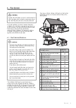
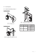
To correctly establish the boiler’s electrical connection, follow
the indications given in the figure and the indications on the
identification label for the terminal strip connections.
DANGER
Disconnect the main electrical supply before beginning any
work and make sure all the necessary safety precautions are
taken into account.
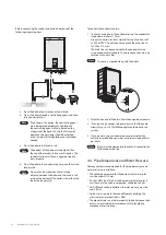
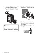
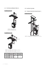
1. Remove the cap “A” from the cable gland on the underside
of the boiler.
A
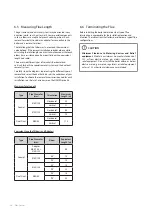
2. Remove the black silicon seal “B” from the cable gland and
thread it onto cable “C”.
B
C
3. Insert cable “C” into the lid “A” together with the seal “B”.
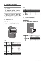
4. Insert all these elements in the cable gland and press on the
lid “A” until the cable is sufficiently fixed in place and the unit
is sealed.
Note
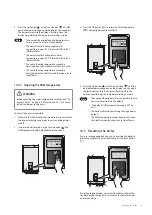
The boiler must be connected to the supply terminals,
which are clearly indicated on the left side of the PCB,
via the cable supplied with the boiler for this purpose.
Live
Earth
Neutral
Note
●
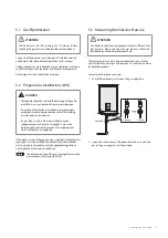
Fuse Size: 5 mm x 20 mm
●
Fuse Rating: 250 V, 3.15 A
DANGER
This appliance must be earthed. Electrocution caused by
touching live parts can be fatal. Before working on the
appliance, turn off the power supply and secure against
restart.
Note
The boiler must be earthed. Connection of the whole
electrical system of the boiler, including any heating
controls to the electrical supply must be through one
common isolator and must be fused 3.15 A maximum.
Summary of Contents for NCB700-42C
Page 69: ...68 Appendices 12 4 Ladder Diagram 3 15A...
Page 73: ...Memo...
Page 74: ...Memo...
Page 75: ...Memo...

