19
Troubleshooting
Appendix A.4 LED Diagnostics for
Communications Between Gateway and
Devices
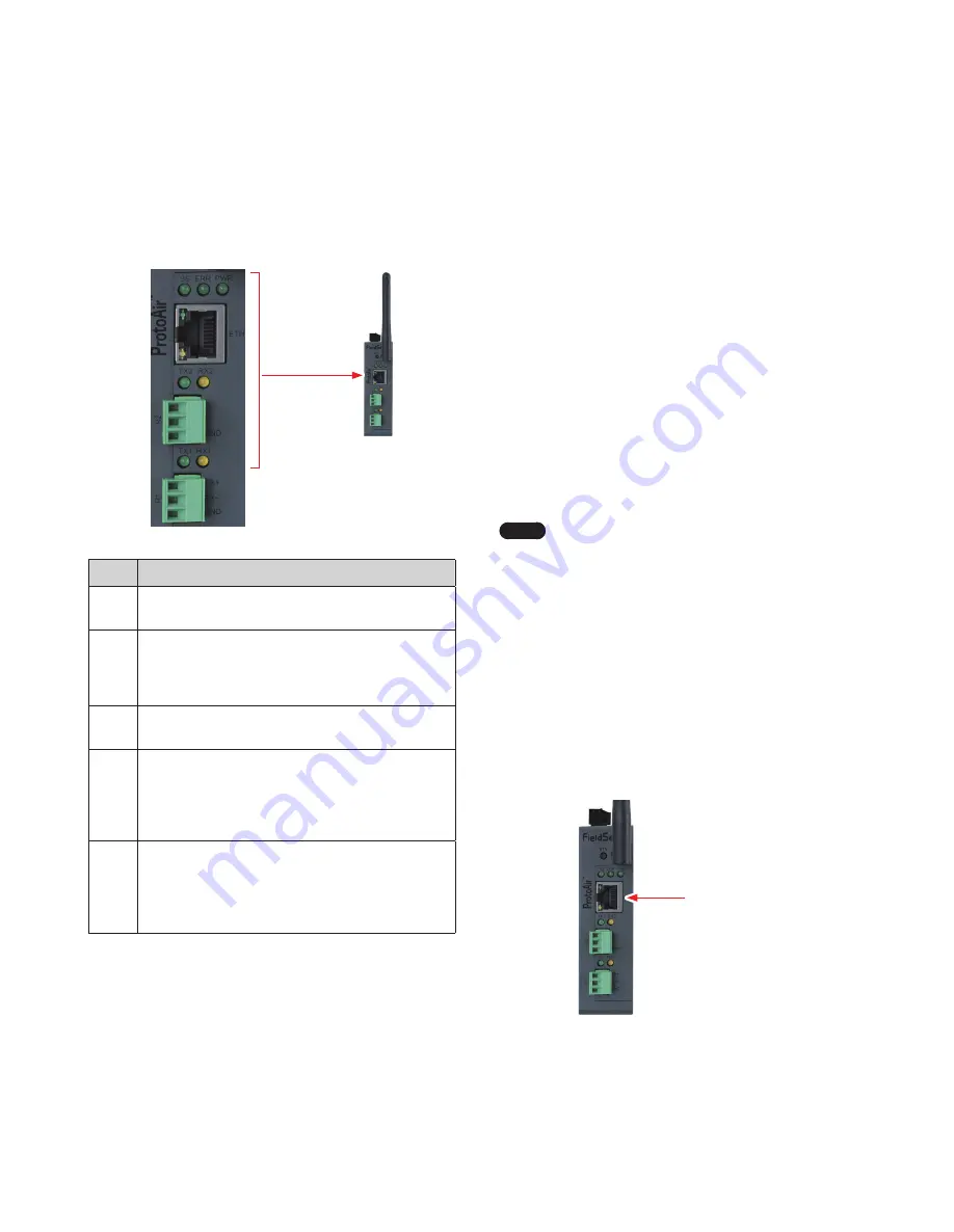
See the diagram below for gateway LED Locations.
Diagnostic LEDs
Tag
Description
SS
The SS LED will light if the unit is not getting a response
from one or more of the configured devices.
ERR
The SYS ERR LED will go on solid indicating there is
a system error. If this occurs, immediately report the
related “system error” shown in the error screen of the
FS-GUI interface to support for evaluation.
PWR
This is the power light and should always show steady
green when the unit is powered.
TX
The TX LED will flash when a message is received on
the serial port on the 3-pin connector.
If the serial port is not used, this LED is non-
operational
. TX1 applies to the R1 connection while
TX2 applies to the R2 connection.
RX
The RX LED will flash when a message is sent on the
serial port on the 3-pin connector.
If the serial port is not used, this LED is non-
operational
. RX1 applies to the R1 connection while
RX2 applies to the R2 connection.
Figure 31: Diagnostic LEDs
Appendix A.5 Taking a FieldServer
Diagnostic Capture
When there is a problem on-site that cannot easily be resolved,
perform a diagnostic capture before contacting support so that
support can quickly solve the problem. There are two methods for
taking diagnostic captures:
●
FieldServer Toolbox:
This method requires installation of the FS Toolbox program. A
FS Toolbox diagnostic capture takes a snapshot of the loaded
configuration files and a log of all the communications on the
serial ports over a specified period of time. If the problem occurs
over an Ethernet connection, then take a Wire Shark capture.
●
Gateway’s FS-GUI Page:
This method doesn’t require downloading software. The
diagnostic capture utilities are embedded in the FS-GUI web
interface. Starting a diagnostic capture takes a snapshot of the
loaded configuration files and a log of all the communications
over a specified period of time. This works for both serial and
Ethernet connections.
Note
The information in the zipped files contains everything
support needs to quickly resolve problems that occur
on-site.
1.
Ethernet Port
Figure 32: Ethernet Port Location
3. Connect a standard Cat-5 Ethernet cable between the PC and
gateway.
Summary of Contents for Modbus/BACnet Gateway
Page 37: ...Memo...
Page 38: ...Memo...


