59
MX 420 Installation and Service Manual
14
15
17
NMEA2 Out A
NMEA2 Out B
TXD
RS-422
Conn.A
RS-232
A
A
10
11
6
5
14
13
2
3
1
15
1A
4A
1Z
1Y
3Z
4Z
4Y
2Z
2Y
3Y
2A
3A
G
G
7
3
2
5
6
DA
DY
RY
RS
RTC
Figure 5.1 Port 2: RS- 422 / RS- 232 Port Schematic
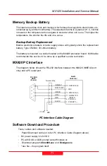
MX420 PC Interface
The diagram below shows the bi-directional (RS-232) interface between the MX420
(NMEA2 port in Cable A) and a PC serial port.
GRN/WHT
SHIELD (BLK)
GREEN
GRAY
13 - NMEA2 IN (B)
1 - GND
12 - NMEA2 IN (A)
17 - NMEA2 TXD
(RS-232)
Mx420
CABLE (A)
PC CONN.
DB9S
(Female)
Terminal Strip
RED
BLACK
+12 VDC
NEG.
2 - PWR IN (+)
3 - PWR RET (-)
NMEA Interface
The MX420 meets the NMEA 0183 version 2.1 electrical standard for marine interface
communications with other marine equipment, such
as:
Radars, Plotters, Autopilots, Fish Finders, etc.
Summary of Contents for MX420
Page 1: ...Installation Service Manual MX420 Navigation System ...
Page 5: ......
Page 8: ...1 MX 420 Installation and Service Manual List of Components SECTION 1 LIST OF COMPONENTS ...
Page 9: ...MX 420 Installation and Service Manual List of Components 2 ...
Page 15: ...MX 420 Installation and Service Manual List of Components 8 ...
Page 17: ...MX420 Installation and Service Manual Technical Specifications 10 ...
Page 24: ...17 MX420 Installation and Service Manual SECTION 3 MECHANICALAND INSTALLATION DRAWINGS ...
Page 25: ...18 MX420 Installation and Service Manual ...
Page 32: ...25 MX420 Installation and Service Manual SECTION 4 ELECTRICALINSTALLATION DRAWINGS ...
Page 33: ...26 MX420 Installation and Service Manual ...
Page 49: ...42 MX420 Installation and Service Manual ...
Page 57: ...50 MX 420 Installation and Service Manual SECTION 5 INSTALLATION NOTES ...


