Chapter 16 Reference
16.3 Ion measurement
226
HORIBA
16.3.3 General characteristics of ion electrode
Ion species which can be measured with ion electrode
The ion electrode only responds to free target ions which exist in the solution under measure-
ment. If the target ions, partially or in whole, are compounds, other forms of ions, or com-
plexes in the solution, a measurement error occurs. Therefore, pretreatment may be required
to carry out so that all the target ions in the solution become free.
(Example)
When fluoride ions are measured, the coexistence of polyvalent metal such as Feand Al in the
sample solution results in the formation of complexes by the fluoride ions and the polyvalent
metal ions. This formation decreases the concentration of free fluoride ions, causing a nomi-
nal measurement error. In such a case, add complex dissociating agent (commercially avail-
able TISAB solution for the fluoride ion electrode) to the sample solution to dissociate the
complexes into fluoride ions before measurement.
Measurable range
The range which maintains a linearity between the logarithm of ion concentration and the dif-
ferences in electric potential is called the measurable range. In general, the measurable range
of ion concentration via the ion electrode is approximately from 10 mol/L to 10 mol/L. The
low -concentration point at which a linearity is lost is called the quantitative limit or the detec-
tion limit.
(Example)
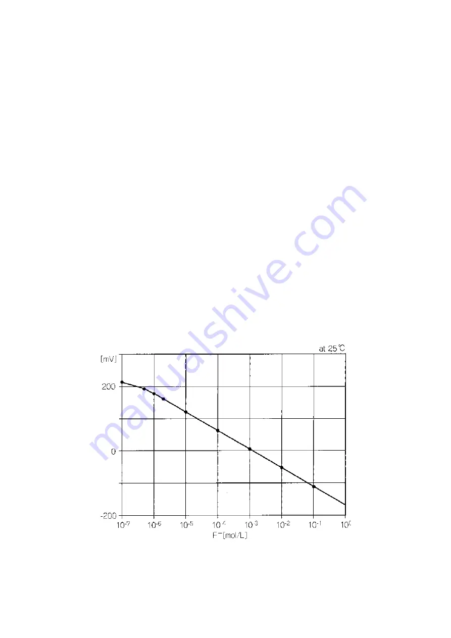
As found from Fig.3, the measurable range for the fluoride ion electrode is 1 to 10 mol/L with
the detection limit being approximately 10 mol/L F
-
.
Fig.3 Calibration curve for fluoride ion electrode
Activity
As the ion concentration in the solution increases, the number of solvent molecules surround-
ing the ions decreases and then the distance between ions becomes shorter. Therefore, the
Supporting electrolyte; 0.1 mol/L KNO
3
Summary of Contents for F-52
Page 2: ......
Page 13: ...TABLE OF CONTENTS X HORIBA...
Page 31: ...Chapter 1 Overview 1 9 Security Function 18 HORIBA...
Page 41: ...Chapter 2 BASIC OPERATIONS 2 5 Navigation Function 28 HORIBA...
Page 103: ...Chapter 5 Ion Measurement F 53 55 5 5 Check Display 90 HORIBA...
Page 125: ...Chapter 8 RESISTIVITY MEASUREMENT F 54 55 8 2 Setting Configuration 112 HORIBA...
Page 165: ...Chapter 11 METER SETTING 11 8 FDA Part 11 Function Audit Trail F 55 152 HORIBA...
Page 187: ...Chapter 13 ANALOG OUTPUT 13 3 Alarm Output 174 HORIBA...
Page 227: ...Chapter 15 Maintenance and troubleshooting 15 2 Troubleshooting 214 HORIBA...


