BHM
12/2/13
NTV-Doc 112
Agreement
:
End user agrees to use this product in compliance with all State and Federal laws. NAV-TV Corp. would not be held liable for
misuse of its product. If you do not agree, please discontinue use immediately and return product to place of purchase. This product is
intended for off-road use and passenger entertainment only.
6 |
P a g e
9.
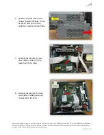
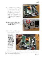
Connect the brown, 3-way ribbon to
the same connector from step 8. Be
certain the ribbon is seated fully,
squarely and securely. The end of the
ribbon labeled ‘From System BD’
connects to the circuit board, the end
labeled ‘To LCD’ goes towards the
LCD. Run both ribbons through the
access holes on the PCM chassis like
shown.
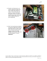
10.
With tin-snips, cut a notch on the
back side of the PCM chassis to run
the LVDS cable through.
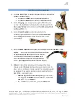
11.
Collect the LVDS cable and relay
circuit board from the ribbon kit.
Connect the
brown T-ribbon
from step 9 and
the LVDS cable to
the relay circuit
board as shown
below. The LVDS
cable can only be
inserted properly
one way. Lastly,
secure the ground
terminal wire
from the LVDS
cable to the Torx
screw indicated
by the yellow
arrow.

